Sony KDL-37NL140 Operating Instructions - Page 10
Hook locations diagram/table, Screw location, TV Model, Hook location, KDL-26NL140
 |
View all Sony KDL-37NL140 manuals
Add to My Manuals
Save this manual to your list of manuals |
Page 10 highlights
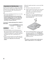
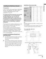
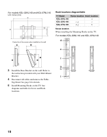
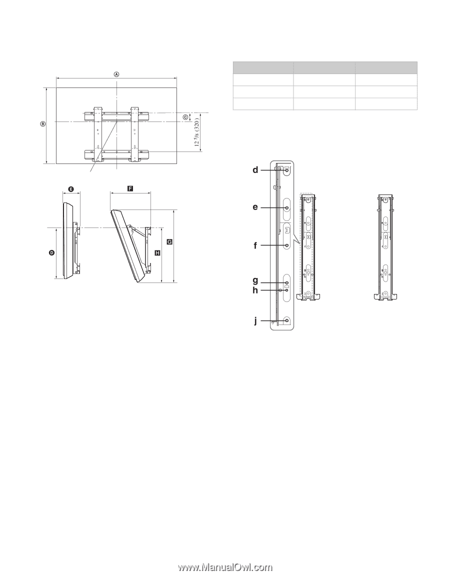
For models KDL-32NL140 and KDL-37NL140 Unit: inches (mm) Hook locations diagram/table TV Model KDL-26NL140 KDL-32NL140 KDL-37NL140 Screw location Hook location - a e, g c d, g b Screw location When installing the Mounting Hooks on the TV. For models KDL-32NL140 and KDL-37NL140 Center line of the screen when installed on the wall 3 Install the Base Bracket on the wall. Refer to the instruction provided with your Wall-Mount Bracket. 4 Disconnect all cables and remove the Table- Top Stand. See page 8 for details. 5 Install Mounting Hooks on the TV. See diagrams and table for Screw and Hook locations. 10
-
 1
1 -
2
-
3
-
4
-
 5
5 -
 6
6 -
 7
7 -
 8
8 -
 9
9 -
 10
10 -
 11
11 -
 12
12 -
 13
13 -
 14
14 -
 15
15 -
16
-
17
-
18
-
19
-
20
-
21
-
22
-
23
-
24
-
25
-
26
-
27
-
28
-
29
-
30
-
31
-
32
-
33
-
34
-
35
-
36
-
37
-
38
-
39
-
40
-
41
-
42
-
43
-
44
-
45
-
46
-
47
-
48
 |
 |
10
3
Install the Base Bracket on the wall. Refer to
the instruction provided with your Wall-Mount
Bracket.
4
Disconnect all cables and remove the Table-
Top Stand. See page 8 for details.
5
Install Mounting Hooks on the TV. See
diagrams and table for Screw and Hook
locations.
Hook locations diagram/table
Screw location
When installing the Mounting Hooks on the TV.
For models KDL-32NL140 and KDL-37NL140
Unit: inches (mm)
Center line of the screen when installed on the wall
TV Model
Screw location
Hook location
KDL-26NL140
-
a
KDL-32NL140
e, g
c
KDL-37NL140
d, g
b
For models KDL-32NL140 and KDL-37NL140