Sony PCV-RX450 System Reference Manual
Sony PCV-RX450 - Vaio Desktop Computer Manual
 |
View all Sony PCV-RX450 manuals
Add to My Manuals
Save this manual to your list of manuals |
Sony PCV-RX450 manual content summary:
- Sony PCV-RX450 | System Reference Manual - Page 1
- Sony PCV-RX450 | System Reference Manual - Page 2
respective owners. Owner's Record The model number and serial number are located on the back of your VAIO® computer. Record the serial number in the space provided here. Refer to the model and serial number when you call your Sony Service Center. Model Number: PCV-RX450/PCV-RX460 Serial Number ii - Sony PCV-RX450 | System Reference Manual - Page 3
0.4 mW(DVD) 0.14 mW (CD) 650-655 nm (DVD) 785 nm (CD) CD-RW Laser Diode Properties Laser Output To change the backup battery, contact your nearest Sony Service Center. ! Caution - The use of optical do not attempt to disassemble the drive cabinet. Refer servicing to qualified personnel only. ! Danger - Sony PCV-RX450 | System Reference Manual - Page 4
de rechange, veuillez contacter votre centre de service Sony le plus près. ! Avertissement - L' service qualifié. ! Danger - Radiation laser visible et invisible si ouvert. Évitez l'exposition directe au faisceau. ! Pour les CD Sony Service Center nearest you, call 1-888-476-6972 in the United - Sony PCV-RX450 | System Reference Manual - Page 5
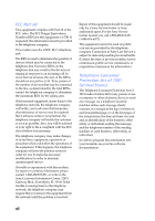
of Conformity Trade Name: SONY Model No.: PCV-RX450/PCV-RX460 Responsible Party: Sony Electronics Inc. Address: 680 Kinderkamack Rd Oradell, NJ 07649 Telephone: 201-930-6970 This phone number is for FCC-related matters only. This device complies with Part 15 of FCC Rules. Operation - Sony PCV-RX450 | System Reference Manual - Page 6
Part 68 -PC, or write to the Sony Customer Information Center, 12451 Gateway Blvd., Fort Myers, FL 33913. If the trouble problem is resolved. Repair of this equipment should be made only by a Sony Service Center or Sony authorized agent. For the Sony Service Center nearest you, call 1-888-4SONY-PC - Sony PCV-RX450 | System Reference Manual - Page 7
Battery You can return your unwanted lithium batteries to your nearest Sony Service Center or Factory Service Center. ✍ In some areas the disposal of lithium batteries manufacturer. Discard used batteries according to the manufacturer's instructions. ! Une batterie non conforme présente un danger - Sony PCV-RX450 | System Reference Manual - Page 8
this equipment may give the telecommunications company cause to request that the user disconnect the equipment. Users should ensure for their own protection that the electrical ground connections of the power utility, telephone lines and internal metallic water pipe system, if present, are connected - Sony PCV-RX450 | System Reference Manual - Page 9
les régions rurales. Avertissement: L'utilisateur ne doit pas tenter de faire ces raccordements luimême; il doit avoir recours à un service d'inspection des installations électriques, ou à un électricien, selon le cas. AVIS: L'indice d'équivalence de la sonnerie (IES) assigné à chaque dispositif - Sony PCV-RX450 | System Reference Manual - Page 10
x - Sony PCV-RX450 | System Reference Manual - Page 11
Identifying Components 1 Front View 2 Drives 3 Buttons and Switches 5 Indicators 6 Connectors 7 Rear View ...8 Icons ...9 I/O Connectors 11 Expansion Slots 15 Chapter 2 - Configuring Your System 17 Accessing the BIOS Setup Utility 18 Changing the Display's Power Management Settings 19 xi - Sony PCV-RX450 | System Reference Manual - Page 12
3.5-inch Internal Hard Disk Drive 41 Removing the Power Supply 45 Replacing the Power Supply 46 Chapter 4 - System Board 47 Connectors and Headers 48 Front Panel Header 48 Floppy Disk Drive Header 49 Memory Module (DIMM) Slots 50 PCI Slots 51 AGP Slot 52 IDE Headers 53 Keyboard and Mouse - Sony PCV-RX450 | System Reference Manual - Page 13
Information ......... 81 About User and Supervisor Passwords 82 Beep Code Error Messages 83 PCI Configuration Status and Error Messages 84 DMA Channel Assignments 85 System I/O Address Map 86 Memory Map 88 IRQ Settings 89 Chapter 8 - Specifications 91 Processor 91 Chipset ...91 PCI - Sony PCV-RX450 | System Reference Manual - Page 14
xiv VAIO® System Reference Manual Floppy Disk Drive and Controller 94 Hard Drives and Controllers 94 Optical Drives 95 System BIOS 96 Index 97 - Sony PCV-RX450 | System Reference Manual - Page 15
Chapter 1 Identifying Components The following sections identify and describe each component that is visible from the exterior of the VAIO® computer. Internal components are identified in the appropriate section of this manual. 1 - Sony PCV-RX450 | System Reference Manual - Page 16
2 VAIO® System Reference Manual Front View - Sony PCV-RX450 | System Reference Manual - Page 17
Identifying Components 3 DVD-ROM Drive CD-RW Drive Floppy Disk Drive Drive Floppy disk drive DVD-ROM drive DVD-ROM read* CD-R/CD-ROM read† CD-RW read‡ CD-RW drive CD-RW read** CD-RW write†† CD-R read‡‡ CD-R write*** CD-ROM read Description 3.5-inch, 1.44 MB. 16X maximum performance 40X maximum - Sony PCV-RX450 | System Reference Manual - Page 18
4 VAIO® System Reference Manual ** Data on a CD-RW is read at a variable transfer rate, ranging from 8X at the innermost track to 20X at the outermost track (the data transfer standard 1X rate is 150 KBps). The average data transfer rate is 14X (2100 KBps). †† The CD-RW writing speed may vary, - Sony PCV-RX450 | System Reference Manual - Page 19
5 Optical disc eject Floppy disk eject Power/Stand by Button or switch Power/Stand by switch Floppy disk eject button Optical disc eject button Description Turns system power on, off, or into Stand by mode. Ejects a floppy disk. Automatically opens and closes the assigned optical drive tray. - Sony PCV-RX450 | System Reference Manual - Page 20
Manual Indicators Floppy disk drive access Hard disk drive access Optical disc drive access Power/Stand by Indicator Power/Stand by indicator Floppy disk drive access indicator Optical drive access indicator Hard disk drive access indicator Description Stand by (red) indicates the computer - Sony PCV-RX450 | System Reference Manual - Page 21
connector. Connects to USB devices. * To connect to a 6-pin i.LINK device, use the i.LINK connector on the back of the system. A 6-pin i.LINK connector can supply power from the computer to the device if the device also has a 6-pin i.LINK connector. A 4-pin i.LINK connector cannot - Sony PCV-RX450 | System Reference Manual - Page 22
8 VAIO® System Reference Manual Rear View Mouse Keyboard USB1 Ethernet Monitor Printer i.LINK (IEEE1394) Serial Headphones Line In Mic Line Power Telephone - Sony PCV-RX450 | System Reference Manual - Page 23
Icons Identifying Components 9 Label Area Icon Description Mouse port Keyboard port USB port Ethernet port Printer/Parallel port Monitor port i.LINK® (IEEE1394) port Serial port Headphones jack - Sony PCV-RX450 | System Reference Manual - Page 24
10 VAIO® System Reference Manual Icon Description Line In jack (audio) Mic (microphone) jack Line jack (for telephone line from service jack) Telephone (for telephone) - Sony PCV-RX450 | System Reference Manual - Page 25
Identifying Components 11 I/O Connectors The following section identifies the various I/O connectors. Keyboard and Mouse Ports The keyboard and mouse ports are physically identical and have the same pinout. They are standard 6-pin PS/2®-type female ports. 2 3 1 4 6 5 USB Ports The USB ports - Sony PCV-RX450 | System Reference Manual - Page 26
12 VAIO® System Reference Manual Printer/Parallel Port The printer/parallel port is a standard 25-pin DB-25 female port. 13 25 14 1 Monitor Port The monitor port is a standard 15-pin female high-density VGA-type port. 10 15 5 11 1 6 - Sony PCV-RX450 | System Reference Manual - Page 27
phone jacks. However, the line jack is for connecting to a telephone line that comes from the wall, and the telephone jack is for connecting the computer to a telephone. Your computer will only have one RJ-11 female phone jack if you have a HomePNA modem installed. The modem installed on your - Sony PCV-RX450 | System Reference Manual - Page 28
14 VAIO® System Reference Manual i.LINK® (IEEE1394) Port The 6-pin i.LINK port on the back of the system can supply power from the computer to a device if the device also has a 6-pin i.LINK port. The 6-pin port supplies 10V to 12V and a maximum power of 6 watts. ✍ i.LINK is a trademark of Sony used - Sony PCV-RX450 | System Reference Manual - Page 29
Identifying Components 15 Expansion Slots There are three PCI slots, two of which are available for expansion (PCI No. 2 and No. 3). The other PCI slot is occupied by the fax/modem card (PCI No. 1). There is one AGP slot that is available for expansion. Slot No. 4 (AGP) Slot No. 3 (PCI) Slot No. - Sony PCV-RX450 | System Reference Manual - Page 30
16 VAIO® System Reference Manual - Sony PCV-RX450 | System Reference Manual - Page 31
Chapter 2 Configuring Your System This chapter contains information on configuring your system. Configuring your system can consist of the following: ❑ Making changes to the BIOS settings ❑ Making changes to the display's power management settings 17 - Sony PCV-RX450 | System Reference Manual - Page 32
Manual Accessing the BIOS Setup Utility You must access the BIOS Setup Utility to make changes to the BIOS settings (see "CMOS Setup Options" on page 73 for information on BIOS settings). ! Before rebooting the system, save and close all open files, and exit open applications. 1 Reboot your computer - Sony PCV-RX450 | System Reference Manual - Page 33
then click Power Options. The Power Options Properties dialog box opens, with the Power Schemes tab displayed. 2 Select the power scheme that is most appropriate for the way you use your computer. To change a power scheme, change the settings for Turn off monitor, Turn off hard disks, System stand - Sony PCV-RX450 | System Reference Manual - Page 34
Reference Manual The Turn off monitor option allows you to specify the period of inactivity (in minutes) that you want to elapse before your monitor turns off when your computer is running on AC power. The display reactivates when you move the mouse or press a key. The Turn off hard disks option - Sony PCV-RX450 | System Reference Manual - Page 35
4 Click the Advanced tab. Configuring Your System 21 5 Select the desired settings. - Sony PCV-RX450 | System Reference Manual - Page 36
22 VAIO® System Reference Manual 6 Click the Hibernate tab. 7 Select the desired settings, and then click OK. - Sony PCV-RX450 | System Reference Manual - Page 37
major components for upgrading, reconfiguring, and troubleshooting the components. ! Before opening the system unit, save and close all open files, exit all open applications, turn off the power to all attached peripheral devices, shut down the computer, and unplug the power cord. ✍ Systems differ - Sony PCV-RX450 | System Reference Manual - Page 38
24 VAIO® System Reference Manual Removing the Side Cover You must remove the side cover to access the system board, add-in cards, power supply, battery, memory, and internal drives. 1 From the rear of the unit, pull the metal tab shown in the next diagram. 2 Pull the top of the side cover away from - Sony PCV-RX450 | System Reference Manual - Page 39
Removing, Installing, and Replacing Components 25 Replacing the Side Cover 1 From the rear of the unit, align the bottom of the side cover so that it slips into the lip on the bottom of the unit. 2 Push the top of the side cover up against the top of the unit until the side cover snaps into - Sony PCV-RX450 | System Reference Manual - Page 40
VAIO® System Reference Manual Installing a PCI Add-In Card ! Before opening the system unit, save and close all open files, exit all open applications, turn off the power to all attached peripheral devices, shut down the computer, and unplug the power the instructions that came with the add-in card). - Sony PCV-RX450 | System Reference Manual - Page 41
computer and follow any instructions that came with the add-in card. Removing a PCI Add-in Card ! Before opening the system unit, save and close all open files, exit all open applications, turn off the power metal part on the metal chassis (preferably the metal part on the power supply) before - Sony PCV-RX450 | System Reference Manual - Page 42
28 VAIO® System Reference Manual 4 Remove the add-in card from the PCI slot and store the card in an anti-static wrapper for future use. ✍ Grasp the card with - Sony PCV-RX450 | System Reference Manual - Page 43
the internal graphics. Your system supports AGP 4X enabled graphics cards. ! Before opening the system unit, save and close all open files, exit all open applications, turn off the power to all attached peripheral devices, shut down the computer, and unplug the power cord. 1 Remove the side cover - Sony PCV-RX450 | System Reference Manual - Page 44
30 VAIO® System Reference Manual 6 Secure the AGP card with the screw removed in step 2. 7 Replace the side cover (see "Replacing the Side Cover" on page 25). 8 Attach the monitor cable to the monitor port on the AGP card. 9 Turn on the computer. 10 Follow the instructions that came with the AGP - Sony PCV-RX450 | System Reference Manual - Page 45
three years, after which the battery may be too weak to power the CMOS memory. ! When you remove the lithium battery, all values stored in the CMOS memory (BIOS setup values and Plug and Play values) may be lost. Although the computer can hold the charge for a short time while replacing the battery - Sony PCV-RX450 | System Reference Manual - Page 46
VAIO® System Reference Manual 8 If necessary, remove any add-in cards (see "Removing a PCI Add-in Card" on page 27) to gain access to the battery. You may also need to disconnect some cables. ! Touch any exposed metal part instructions ✍ The Sony CR2032 battery power cord and turn on the computer. - Sony PCV-RX450 | System Reference Manual - Page 47
: Check date and time settings." appears during the reboot sequence, press F2 during the reboot process to access the BIOS Setup Utility. If no error message displays, the computer's BIOS settings were retained during the battery replacement and you can skip the remaining steps. 17 Refer to the list - Sony PCV-RX450 | System Reference Manual - Page 48
34 VAIO® System Reference Manual Installing System Memory ! Before opening the system unit, save and close all open files, exit all open applications, turn off the power to all attached peripheral devices, shut down the computer, and unplug the power cord. 1 Choose the size of the memory module - Sony PCV-RX450 | System Reference Manual - Page 49
the appropriate slot, noting the location of pin 1 on the module and pin 1 on the slot. Press down here Handles Pin 1 side DIMM 2 DIMM 1 Memory module (DIMM) 1 Indicates pin 1 8 Carefully but firmly insert the edge of the module into the slot. 9 Press down firmly and evenly at both corners until - Sony PCV-RX450 | System Reference Manual - Page 50
36 VAIO® System Reference Manual 10 Replace the power supply (see "Replacing the Power Supply" on page 46). 11 Replace the side cover (see "Replacing the Side Cover" on page 25). 12 Reconnect the power cord and turn on the computer. Your computer automatically recognizes the extra memory and will - Sony PCV-RX450 | System Reference Manual - Page 51
Side Cover" on page 24). ✍ The memory modules are located beneath the power supply. You need to remove the power supply to reach the memory modules. 2 Remove the power supply (see "Removing the Power Supply" on page 45). ! Touch any exposed metal part of the chassis to discharge static electricity - Sony PCV-RX450 | System Reference Manual - Page 52
38 VAIO® System Reference Manual 4 Reach around each side of the power supply and push down the handle on each side of the memory module to eject the module from its slot. Push out Handles 5 Grasp one edge of the memory module and lift out. Store the module in a static-free bag. - Sony PCV-RX450 | System Reference Manual - Page 53
. ! Before opening the system unit, save and close all open files, exit all open applications, turn off the power to all attached peripheral devices, shut down the computer, and unplug the power cord. 1 Remove the side cover (see "Removing the Side Cover" on page 24). 2 Locate the slot whose cover - Sony PCV-RX450 | System Reference Manual - Page 54
40 VAIO® System Reference Manual Covering an Open I/O Slot Slot covers prevent air from escaping through the empty hole. If air escapes, the components inside the computer cannot be properly cooled. This may damage some components, especially the main processor (which generates the most heat). ! - Sony PCV-RX450 | System Reference Manual - Page 55
(CTO) systems, may already have a second hard disk drive installed. ! Before opening the system unit, save and close all open files, exit all open applications, turn off the power to all attached peripheral devices, shut down the computer, and unplug the power cord. 1 Configure the jumpers on the - Sony PCV-RX450 | System Reference Manual - Page 56
42 VAIO® System Reference Manual 3 Disconnect the drive connector (A in diagram). Drive connector A B Power supply connector Tab C Disk drive holder 4 Disconnect the power connector (B in diagram). 5 Pull out on the tab (C) that secures the drive holder to the chassis. - Sony PCV-RX450 | System Reference Manual - Page 57
Removing, Installing, and Replacing Components 43 6 Slide the drive holder up and out. 7 Slide the new drive into the bottom part of the drive holder and align the holes on each side of the drive holder. 8 Secure the drive to the drive holder using screws in each of the two holes on each side of - Sony PCV-RX450 | System Reference Manual - Page 58
44 VAIO® System Reference Manual 10 Push in on the tab (A) to securely latch the holder to the chassis. Drive connectors C E B D Power connectors A Tab Disk drive holder 11 Connect the inner drive cable connector (B) to the first drive. 12 Connect the outer drive cable connector(C) to the - Sony PCV-RX450 | System Reference Manual - Page 59
the Power Supply You remove the power supply when you insert a memory module (see "Installing System Memory" on page 34). ! Before opening the system unit, save and close all open files, exit all open applications, turn off the power to all attached peripheral devices, shut down the computer, and - Sony PCV-RX450 | System Reference Manual - Page 60
46 VAIO® System Reference Manual Replacing the Power Supply 1 Rotate the power supply down and slide it into the chassis along the rails to each side of the chassis until the tab snaps into position. 2 Replace the screw that secures the power supply to the rear of the chassis. - Sony PCV-RX450 | System Reference Manual - Page 61
CPU Therm Keyboard, Mouse USB1, Ethernet Printer (top) Monitor, i.LINK i.LINK Header (to front panel) Serial (top) Mic in, Line in, Line out Aux-In (not used) CD-In (to DVD-ROM drive) WOL_CON (not used) Slot No. 4 (AGP) Slot No. 3 (PCI) Slot No. 2 (PCI) Slot No. 1 (PCI) Battery Power Supply - Sony PCV-RX450 | System Reference Manual - Page 62
48 VAIO® System Reference Manual Connectors and Headers Front Panel Header The front panel Name Description CD-LED Connects to the CD/DVD drive access light on the front panel. PWR LED Connects to the power-on indicator light on the front panel HD LED Connects to the hard disk drive access light - Sony PCV-RX450 | System Reference Manual - Page 63
Floppy Disk Drive Header System Board 49 Key (pin 5) 1 2 33 34 - Sony PCV-RX450 | System Reference Manual - Page 64
DIMM1 DIMM2 50 VAIO® System Reference Manual Memory Module (DIMM) Slots Both sides of each Dual Inline Memory Module (DIMM) look very similar. The side with pin 1 has a small "1" to the left of pin 1. Be sure to orient a DIMM correctly in the DIMM - Sony PCV-RX450 | System Reference Manual - Page 65
by the fax/ modem card (No. 1). Your modem may look different depending on whether it is a Lucent modem or an HPNA modem. The PCI slots support 32-bit 5 V and Universal (3.3/5 V) PCI add-in cards. Slot No. 3 (PCI) Slot No. 2 (PCI) Slot No. 1 (PCI) A1 A49 A52 A62 B1 B49 B52 B62 - Sony PCV-RX450 | System Reference Manual - Page 66
Reference Manual AGP Slot There is one AGP slot (slot No. 4). This slot enables you to install an AGP card to enhance your system's graphics capabilities. The length of the AGP card should not exceed 9.05 inches. ✍ Installing an AGP card disables the internal graphics. Your system supports AGP - Sony PCV-RX450 | System Reference Manual - Page 67
System Board 53 IDE Headers There are two IDE (Integrated Drive Electronics) headers on the system board: a Primary IDE and a Secondary IDE header. Each 40-pin IDE header supports up to two IDE drives using a ribbon cable with two connectors. Secondary IDE header Primary IDE header 40 39 2 1 - Sony PCV-RX450 | System Reference Manual - Page 68
54 VAIO® System Reference Manual Keyboard and Mouse Ports The keyboard port and the mouse port are 6-pin female PS/2-type (mini-DIN) ports. They have identical pinouts. Mouse 1 6 2 5 3 4 1 6 2 5 3 4 Keyboard Keyboard and Mouse Ports Pin Signal Name 1 DATA 2 NC 3 LOGIC GND 4 + - Sony PCV-RX450 | System Reference Manual - Page 69
front panel. If more USB devices are needed, connect an external hub to any USB port. There is one Ethernet port is used to connect to a 100Base-TX/10Base-T Ethernet network. Ethernet USB1 USBHEAD (connects to USB2 and USB3 on front panel) Pin Signal Name 1 NC 2 NC 3 NC 4 NC (Key) 5 USB - Sony PCV-RX450 | System Reference Manual - Page 70
56 VAIO® System Reference Manual USBHEAD (connects to USB2 and USB3 on front panel) (cont.) 11 Ground 12 Ground * Uses over-current protector. USB1 and Ethernet port Pin Signal Name 1 ACTLEDP 2 ACTLEDN 3 LILEDP 4 LILEDN 5 TXPCON 6 TXNCON 7 RXPCON 8 LANP5 9 LANP5 10 RXNCON 11 - Sony PCV-RX450 | System Reference Manual - Page 71
-type connector. The 6-pin i.LINK connector on the back of the system can supply power from the computer to a device if the device also has a 6-pin i.LINK connector. The 6-pin connector supplies 10V to 12V and a maximum power of 6 watts. 13 Printer 1 25 14 5 1 15 11 Monitor 6-pin i.LINK - Sony PCV-RX450 | System Reference Manual - Page 72
58 VAIO® System Reference Manual Printer connector (cont.) Pin Signal Name 13 SELECT 14 AUTO-FEED 15 ERROR 16 INIT 17 SELECT-IN 18 LOGIC GND 19 LOGIC GND 20 - Sony PCV-RX450 | System Reference Manual - Page 73
i.LINK connector Pin Signal Name 1 VP (Power)* 2 Ground 3 TPB 4 TPB 5 TPA 6 TPA * Uses over-current protector. System Board 59 - Sony PCV-RX450 | System Reference Manual - Page 74
60 VAIO® System Reference Manual i.LINK Header i.LINK header is an 8-pin header that connects to a 4-pin i.LINK connector that is connector on front panel) i.LINK header Pin Signal Name 1 Shell Ground 2 Ground 3 TPA 4 TPA 5 TPB 6 TPB 7 Ground 8 VP (Power)* * Uses over-current protector. - Sony PCV-RX450 | System Reference Manual - Page 75
System Board 61 Serial Port, Headphones, Line In, and Mic Connectors The serial connector is a DB-9 male connector. The headphones, line in, and mic jacks are stereo mini-jacks (3.5 mm). The headphones jack connects to headphones. The line in jack connects to a stereo audio source (not an audio - Sony PCV-RX450 | System Reference Manual - Page 76
62 VAIO® System Reference Manual Headphones Audio Right Out Audio Left Out Line In Audio Right In L Imbalance Audio Left In Mic Electret bias voltage MIC imbalance MIC mono in - Sony PCV-RX450 | System Reference Manual - Page 77
System Board 63 Power Supply Header The power supply header on the system board connects to the power supply connector labelled P1. 10 20 1 11 - Sony PCV-RX450 | System Reference Manual - Page 78
64 VAIO® System Reference Manual Fan Headers The CPU-FAN and PWR-FAN headers are 1 x 3-pin straight headers. The CPU_FAN header connects to the CPU fan and controls the CPU cooling. The PWR-FAN header is a 1 x 3-pin straight header. The PWR-FAN connects to the power supply and controls the power - Sony PCV-RX450 | System Reference Manual - Page 79
System Board 65 CD-In Header The CD-In header on the system board is a 1 x 4-pin header that connects to the DVD-ROM drive. CD-In 4 1 CD-In header Pin Signal Name 1 Left Line In 2 Ground 3 Ground 4 Right Line In - Sony PCV-RX450 | System Reference Manual - Page 80
66 VAIO® System Reference Manual Wake On LAN (WOL-CON) Header The Wake On LAN header (WOL-CON) on the system board is a 3-pin header. It is not used. Wake On Lan Wake On LAN header Pin Signal Name 1 +5Vsb 2 Ground 3 WOL signal - Sony PCV-RX450 | System Reference Manual - Page 81
System Board 67 AUX Audio Header The AUX Audio header is a 4 pin standard 2mm single line header that connects to the AUX Audio signal input (not used). AUX Audio AUX Audio header Pin Signal Name 1 Left Line In 2 Ground 3 Ground 4 Right Line In - Sony PCV-RX450 | System Reference Manual - Page 82
68 VAIO® System Reference Manual Configuration Jumper (CMOS CLR) There is one user-configurable jumper for CMOS Clear. The computer ships with CMOS Clear in the Normal position. Do not change the position of this jumper unless directed by a technical support person. CMOS Clear 12 3 CMOS Clear - Sony PCV-RX450 | System Reference Manual - Page 83
either installed with a HomePNA modem or Lucent 1648 modem depending on the configuration you purchased. To determine the modem installed on your computer, locate the RJ-11 jacks on the back of your system. If one RJ-11 jack exists, you have a HomePNA modem; if two RJ-11 - Sony PCV-RX450 | System Reference Manual - Page 84
70 VAIO® System Reference Manual HomePNA Modem The HomePNA standard uses frequency division multiplexing (FDM) Solutions: Using the HomePNA Modem with Sony VAIO Computers documentation that accompanied your computer(s) and the installation instructions that accompanied the HomePNA device(s) for - Sony PCV-RX450 | System Reference Manual - Page 85
Fax/Modem Card 71 Lucent 1648 Modem There are two RJ-11 jacks: one to connect a telephone line, and one to connect a phone. Telephone Line Connectors Name Telephone Line Connector Type RJ-11 RJ-11 Description Connects to phone Connects to telephone line - Sony PCV-RX450 | System Reference Manual - Page 86
72 VAIO® System Reference Manual - Sony PCV-RX450 | System Reference Manual - Page 87
BIOS Setup Utility (see "Accessing the BIOS Setup Utility" on page 18). The Award BIOS setup has five menu items on the menu bar. These are: ❑ Main ❑ Advanced ❑ Power are shown without brackets directly below the default option in this guide. The available options are listed in the order they occur - Sony PCV-RX450 | System Reference Manual - Page 88
74 VAIO® System Reference Manual Press F10 to save the changes and exit, or press Esc to discard the changes. Follow the on-screen prompts for other choices. The bottom of the screen presents a summary of the keys to use for navigation and control. - Sony PCV-RX450 | System Reference Manual - Page 89
-Menus" on page 76) Secondary Master (see "IDE Sub-Menus" on page 76) Secondary Slave (see "IDE Sub-Menus" on page 76) Supervisor Password [Disabled] User Password [Disabled] Installed Memory 128 MB BIOS Revision 1002 - Sony PCV-RX450 | System Reference Manual - Page 90
As†† [Auto] User Type HDD CD-ROM LS-120 ZIP-100 MO Other ATAPI Device None [LBA] Large Normal Match Partition Table Manual [1024] [255] [63] 8422 MB 30735 MB [Maximum] Disabled 2 Sectors 4 Sectors 8 Sectors 16 Sectors 32 Sectors [Disabled] Enabled [4] [5] [Auto] Floppy Hard Disk * This option - Sony PCV-RX450 | System Reference Manual - Page 91
CMOS Setup Options 77 Advanced Screen CPU Speed 1000 MHz (PCV-RX450) 1200 MHz (PCV-RX460) I/O Device Configuration Onboard AC97 Audio Controller [Enabled] Disabled Onboard 1394 Controller [Enabled] Disabled Onboard LAN Controller [Enabled] Disabled Onboard Serial Port 1 [3F8H/IRQ4] 2F8H/ - Sony PCV-RX450 | System Reference Manual - Page 92
78 VAIO® System Reference Manual Power Screen Power Up Control AC Power Loss Restart Power Up On Modem Act Wake On LAN Hardware Monitor MB Temperature CPU Temperature CPU Fan Speed Power Fan Speed VCORE Voltage +3.3V Voltage +5V Voltage +12V Voltage -12V Voltage [Disabled] Enabled [Disabled] - Sony PCV-RX450 | System Reference Manual - Page 93
Boot Screen 1. ATAPI CD-ROM 2. Removable Device 3. IDE Hard Drive 4. Other Boot Device 5. Silent Boot CMOS Setup Options 79 [(displays installed drive)] Disabled [Legacy Floppy] LS120 ZIP-100 ATAPI MO Disabled [(displays installed drive)] Disabled [Disabled] Network SCSI Boot Device [Enabled] - Sony PCV-RX450 | System Reference Manual - Page 94
80 VAIO® System Reference Manual Exit Screen Exit Saving Changes Exit Discarding Changes Load Setup Defaults Discard Changes Save Changes - Sony PCV-RX450 | System Reference Manual - Page 95
Information This chapter contains information on the following subjects: ❑ User and Supervisor password ❑ Beep code error messages ❑ PCI configuration status and error messages ❑ DMA channel assignments ❑ IRQ assignments ❑ System I/O address map ❑ Memory map ❑ PCI configuration space map 81 - Sony PCV-RX450 | System Reference Manual - Page 96
82 VAIO® System Reference Manual About User and Supervisor Passwords The system allows you to specify up to two passwords (a User password and a Supervisor password) in the CMOS Setup Utility. The User password is required; the Supervisor password is optional. Access to the CMOS Setup Utility - Sony PCV-RX450 | System Reference Manual - Page 97
bootup, a single short beep signifies that the system is OK. Other beep patterns signify errors. The number of beeps indicates the specific error that occurred. The Sony Online Support technical representative will need to know how many beeps your system produces if there is an error, so be sure to - Sony PCV-RX450 | System Reference Manual - Page 98
VAIO® System Reference Manual PCI Configuration Status and Error Messages The following is a list of status and error messages that may appear on your system from time to time. Message Floppy Disk primary boot device (hard disk drive, floppy disk drive, CD-ROM drive, or network drive) could not be - Sony PCV-RX450 | System Reference Manual - Page 99
factory default values. The Microsoft® Windows® Me operating system reassigns resources to best meet the needs of a particular configuration. DMA Channel 2 4 Default Assignment Standard floppy disk controller Direct memory access controller - Sony PCV-RX450 | System Reference Manual - Page 100
Keyboard Motherboard resources System CMOS/real time clock Motherboard resources Direct memory access controller Motherboard resources Direct memory access controller Programmable interrupt controller Motherboard resources Direct memory access controller Motherboard resources Numeric data processor - Sony PCV-RX450 | System Reference Manual - Page 101
5513 Dual PCI IDE Controller Primary IDE controller (dual fifo) Standard Floppy Disk Controller Communications port (COM1) Motherboard resources Motherboard resources PCI bus Realtek RTL8139 Family PCI Fast Ethernet NIC Lucent WDM Communication Device* Lucent WDM Communication Device* BCM V.90 56K - Sony PCV-RX450 | System Reference Manual - Page 102
88 VAIO® System Reference Manual Memory Map Address range 00000000h-0009FFFFh 000A0000h-000AFFFFh 000B0000h Port SiS 7018 Audio Driver SiS 7001 PCI to USB Open Host Controller PCI standard host CPU bridge System board extension for ACPI BIOS Motherboard resources Motherboard resources * For HPNA - Sony PCV-RX450 | System Reference Manual - Page 103
Keyboard Floppy Disk Ethernet NIC 09 ACPI IRQ Holder for PCI IRQ Steering 09 SCI IRQ used by ACPI bus 10 SiS 7018 Audio Driver 10 ACPI IRQ Holder for PCI IRQ Steering 11 SiS 730S 11 ACPI IRQ Holder for PCI IRQ Steering 12 PS/2 Compatible Mouse Port 13 Numeric data processor - Sony PCV-RX450 | System Reference Manual - Page 104
90 VAIO® System Reference Manual - Sony PCV-RX450 | System Reference Manual - Page 105
This chapter describes the technical specifications for the Sony PCV-RX450/PCV-RX460 computer. Processor PCV-RX460: 1.2 GHz* AMD Athlon™ processor (with 200 MHz FSB) PCV-RX450: 1 GHz AMD Athlon™ processor (with 200 MHz FSB) * GHz denotes microprocessor internal clock speed. Other factors - Sony PCV-RX450 | System Reference Manual - Page 106
92 VAIO® System Reference Manual DIMM Configurations DIMM1* 0, 8, 16, 32, 64, 128, 256 DIMM2* 0, 8, 16, 32, 64, 128, 256 * The PCV-RX450/PCV-RX460 is shipped with 128 MB. SDRAM is expandable to 512 MB. Computer SDRAM is unbuffered DIMM, specification Rev. 1.0 or later. Supports SDRAM memory. - Sony PCV-RX450 | System Reference Manual - Page 107
Specifications ) Communications Modem Fax i.LINK® (IEEE1394) Ethernet HomePNA V.90-compatible data/fax modem* 14 permissible data speed is 53 Kbps during download transmissions. Actual data speeds may vary, supports two ATA100 IDE drives) One 4-pin connector on front panel One 6-pin connector - Sony PCV-RX450 | System Reference Manual - Page 108
VAIO® System Reference Manual Floppy Disk Drive and Controller Drive Floppy disk controller Floppy disk drive Description 82077-compatible (supports up to 2.88 MB) 3.5-inch, 1.44 MB. Hard Drives and Controllers Drive EIDE controller IDE hard drive* Description Supports up to four EIDE drives - Sony PCV-RX450 | System Reference Manual - Page 109
Specifications 95 Optical Drives Drive DVD-ROM drive DVD-ROM read* CD-R/CD-ROM read† CD-RW read‡ CD-RW drive CD-RW read** CD-RW write†† CD-R read‡‡ CD-R write*** CD-ROM read Description 16X maximum performance 40X maximum performance 32X maximum performance 20X maximum performance 8X maximum - Sony PCV-RX450 | System Reference Manual - Page 110
96 VAIO® System Reference Manual System BIOS Make and model ROM Passwords Power management Advanced features Plug and Play devices Special features Award-based 2 MB flash-ROM User and supervisor passwords supported APM 1.2 ACPI-1.0 compliant hardware for use with APM and PNP BIOS APIs Supported - Sony PCV-RX450 | System Reference Manual - Page 111
options 73 power screen 78 screens 73 BIOS specifications 96 C card modem 71 CD-In connector 65 CD-RW drive location of 3 performance of discs 3, 95 CMOS - See BIOS CMOS Clear configuration jumper 68 codes, beeps 83 COM1 port - See SERIAL connector communications, specifications 93 computer lithium - Sony PCV-RX450 | System Reference Manual - Page 112
40 icons, description of 9 IDE connectors 53 IEEE1394 - See i.LINK installing 3.5-inch hard disk drive 41 add-in card 26 system memory 34 interference v IRQ settings 89 K KEYBOARD connector 11, 54 L L2 cache specifications 92 LINE IN connector 13, 61 lithium battery disposal vii replacing 31 safety - Sony PCV-RX450 | System Reference Manual - Page 113
39 specifications AGP bus 91 audio 93 BIOS 96 chipset 91 communications 93 DIMM configurations 92 floppy disk drive and controller 94 graphics 92 hard drives and controllers 94 I/O and expansion slots 93 L2 cache 92 memory module 92 optical drives 95 PCI bus 91 processor 91 system BIOS 96 status - Sony PCV-RX450 | System Reference Manual - Page 114
100 VAIO® System Reference Manual T TELEPHONE connector 13 Telephone Consumer Protection Act of 1991 vi TV interference v U USB connectors 7, 11, 55 user password 82
-
 1
1 -
 2
2 -
 3
3 -
 4
4 -
 5
5 -
 6
6 -
 7
7 -
8
-
9
-
10
-
11
-
12
-
13
-
14
-
15
-
16
-
17
-
18
-
19
-
20
-
21
-
22
-
23
-
24
-
25
-
26
-
27
-
28
-
29
-
30
-
31
-
32
-
33
-
34
-
35
-
36
-
37
-
38
-
39
-
40
-
41
-
42
-
43
-
44
-
45
-
46
-
47
-
48
-
49
-
50
-
51
-
52
-
53
-
54
-
55
-
56
-
57
-
58
-
59
-
60
-
61
-
62
-
63
-
64
-
65
-
66
-
67
-
68
-
69
-
70
-
71
-
72
-
73
-
74
-
75
-
76
-
77
-
78
-
79
-
80
-
81
-
82
-
83
-
84
-
85
-
86
-
87
-
88
-
89
-
90
-
91
-
92
-
93
-
94
-
95
-
96
-
97
-
98
-
99
-
100
-
101
-
102
-
103
-
104
-
105
-
106
-
107
-
108
-
109
-
110
-
111
-
112
-
113
-
114
 |
 |
