Sony PRS-600 Service Manual - Page 10
Prs-600, Electrical, Adjustment - case
 |
UPC - 705105886336
View all Sony PRS-600 manuals
Add to My Manuals
Save this manual to your list of manuals |
Page 10 highlights
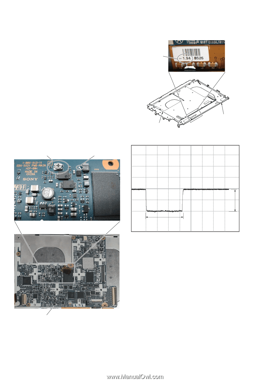
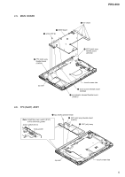
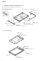
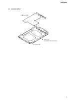
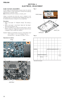
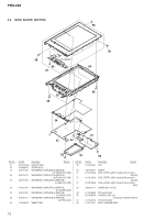
PRS-600 SECTION 4 ELECTRICAL ADJUSTMENT VCOM VOLTAGE ADJUSTMENT VCOM voltage for the Ink Indicator Element varies for each Ink Indicator Element. VCOM adjustment is required when replacing MAIN board or CHASSIS_ASSY. Note: Ink Indicator Element is included in CHASSIS_ASSY. Voltage is generated only when the screen is changed, so the adjustment needs to be performed while changing the screen. Use the slideshow function to change the screen sequentially. Fig. 1: VCOM voltage Procedure: 1. Refer to test mode "17. Slideshow Setting". The setting is "ON". 2. Refer to test mode "1. Test Panel". Enter the "Test Panel", check that the slideshow start. 3. Observe the TP940 on an oscilloscope (refer to Fig. 2), and use RV901 to adjust the voltage that is generated when the screen is changed so that it satisfies the standard. Standard: Written on the flexible card wire of the display panel with a marker. (-1 V to -2.5 V) (refer to Fig. 1) (In case of Fig. 1: The value of VCOM is -1.94 V.) Adjustment Location: RV901 TP940 MAIN board Fig. 2: chassis_assy 660 ms 500 mV/DIV, 200 ms/DIV 1 Vp-p MAIN board 10
-
 1
1 -
2
-
3
-
4
-
 5
5 -
 6
6 -
 7
7 -
 8
8 -
 9
9 -
 10
10 -
 11
11 -
 12
12 -
 13
13 -
 14
14
 |
 |