Sony PRS-600 Service Manual - Page 6
Ornament_bottom_assy, Ornament_top_assy, Case_upper_assy
 |
UPC - 705105886336
View all Sony PRS-600 manuals
Add to My Manuals
Save this manual to your list of manuals |
Page 6 highlights
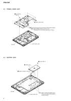
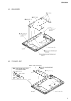
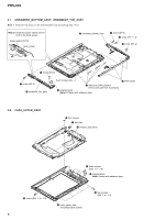
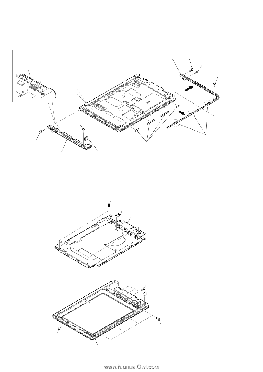
PRS-600 2-7. ORNAMENT_BOTTOM_ASSY, ORNAMENT_TOP_ASSY Note 1: Ornament top assy can be disassembled only by working step 7 to 9. Note 2: Install the power switch (S101) to fit to the knob_power. power switch (S101) knob_power 6 ornament_bottom_assy 1 screw (M1.4) 2 screw (P1.7 u 3) 1 screw (M1.4) 4 4 7 screw (M1.4) 7 screw (M1.4) 9 ornament_top_assy touch screen side 3 three claws 5 adhesive (ORN_bottom) (This is one part from 4 sections) 8 magnet block Note 3: Pasted with adhesive tape. 2-8. CASE_UPPER_ASSY 3 four screws 1 two clips 4 chassis_assy block 2 three screws (DIA. 1.4 u 1.8) 5 magnet block Note: Pasted with adhesive tape. 2 screw (DIA. 1.4 u 1.8) 2 four screws (DIA. 1.4 u 1.8) 6 case_upper_assy (including touch screen) 6
-
 1
1 -
 2
2 -
 3
3 -
 4
4 -
 5
5 -
 6
6 -
 7
7 -
 8
8 -
 9
9 -
 10
10 -
 11
11 -
 12
12 -
13
-
14
 |
 |
PRS-600
6
2-7.
ORNAMENT_BOTTOM_ASSY,
ORNAMENT_TOP_ASSY
Note 1
: Ornament top assy can be disassembled only by working step 7 to 9.
2-8.
CASE_UPPER_ASSY
2
screw (DIA. 1.4
u
1.8)
2
four screws
(DIA. 1.4
u
1.8)
3
four screws
4
chassis_assy block
2
three screws
(DIA. 1.4
u
1.8)
5
magnet block
Note:
Pasted with adhesive tape.
6
case_upper_assy
(including touch screen)
1
two clips
1
screw (M1.4)
1
screw (M1.4)
3
three claws
4
4
6
ornament_bottom_assy
9
ornament_top_assy
7
screw (M1.4)
7
screw (M1.4)
8
magnet block
Note 3:
Pasted with adhesive tape.
2
screw (P1.7
u
3)
power switch (S101)
knob_power
Note 2:
Install the power switch (S101)
to fit to the knob_power.
touch screen side
5
adhesive (ORN_bottom)
(This is one part from 4 sections)