Sony PRS650SC Service Manual - Page 3
Prs-650, Disassembly - prs 650 case
 |
View all Sony PRS650SC manuals
Add to My Manuals
Save this manual to your list of manuals |
Page 3 highlights
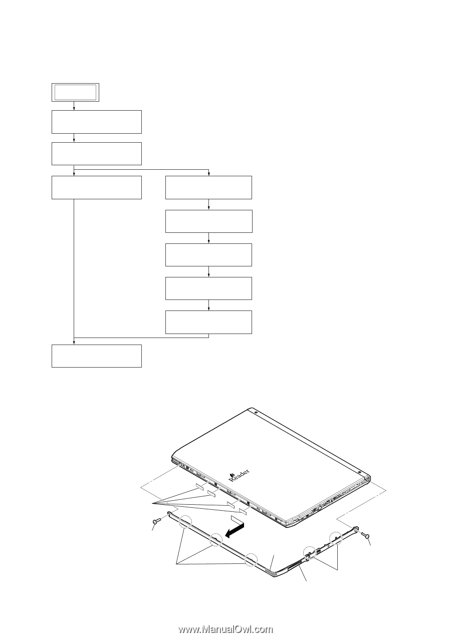
SECTION 2 DISASSEMBLY • This set can be disassembled in the order shown below. 2-1. DISASSEMBLY FLOW SET Note 1: Please detach the STYLUS ASSY beforehand. Note 2: Please take care not to lose the STYLUS ASSY. 2-2. ORNAMENT ASSY (Page 3) 2-3. CASE (REAR) BLOCK (Page 4) 2-4. BATTERY ASSY (BAT1) (Page 4) 2-5. FRAME (REAR) ASSY (Page 5) 2-6. ORNAMENT (T) ASSY (Page 5) 2-7. CASE ASSY (Page 6) 2-8. LED board (Page 6) 2-9. MAIN board (Page 7) 2-10. PANEL ASSY (Page 7) Note: Follow the disassembly procedure in the numerical order given. 2-2. ORNAMENT ASSY PRS-650 6 four adhesive sheets (ornament) 2 shaft screw 5 three claws 4 adhesive sheet (ornament) 1 screw (M1.4) - Rear side view - 3 two claws 7 ornament assy 3
-
 1
1 -
 2
2 -
 3
3 -
 4
4 -
 5
5 -
 6
6 -
 7
7 -
 8
8 -
 9
9 -
10
-
11
-
12
-
13
-
14
-
15
-
16
 |
 |
PRS-650
3
SECTION
2
DISASSEMBLY
•
This set can be disassembled in the order shown below.
2-1.
DISASSEMBLY
FLOW
Note:
Follow the disassembly procedure in the numerical order given.
2-2.
ORNAMENT
ASSY
2-4. BATTERY ASSY (BAT1)
(Page 4)
2-5. FRAME (REAR) ASSY
(Page 5)
2-7. CASE ASSY
(Page 6)
2-8. LED board
(Page 6)
2-9. MAIN board
(Page 7)
2-3. CASE (REAR) BLOCK
(Page 4)
2-6. ORNAMENT (T) ASSY
(Page 5)
2-10. PANEL ASSY
(Page 7)
SET
2-2. ORNAMENT ASSY
(Page 3)
Note 1:
Please detach the STYLUS ASSY beforehand.
Note 2:
Please take care not to lose the STYLUS ASSY.
1
screw
(M1.4)
2
shaft screw
3
two claws
5
three claws
7
ornament assy
6
four adhesive sheets
(ornament)
adhesive sheet
(ornament)
4
– Rear side view –