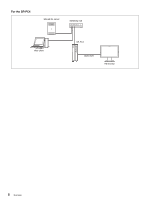
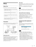
Sony SRPC5 Product Manual (SRMASTER: SRPC4 / SRPC5 Operation Manual) - Page 10
Rear, VTR I/F OUTPUT connector
 |
View all Sony SRPC5 manuals
Add to My Manuals
Save this manual to your list of manuals |
Page 10 highlights
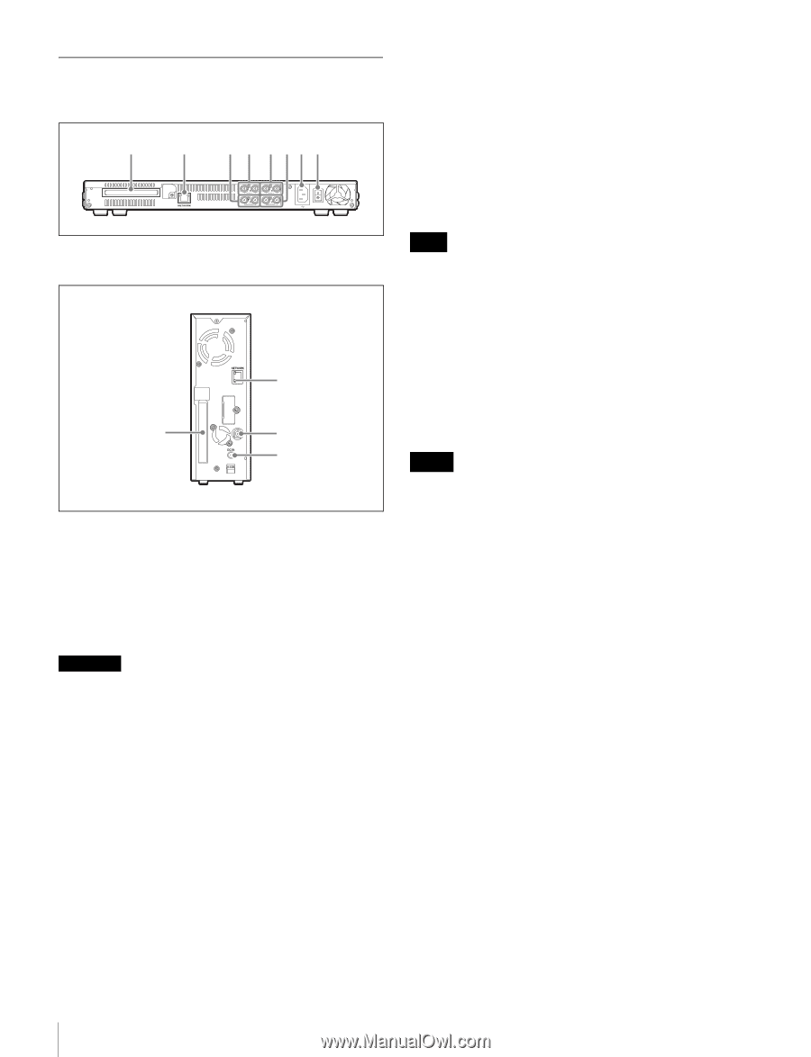
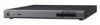
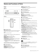
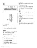
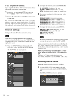
Rear SRPC-5 1 2 3 4 5 678 g [PC5] AC IN connector Connect the power cord here for connection to a power outlet. h [PC5] Main power switch Use this to turn the power supply on/off. During regular use of the unit, leave the main power switch in the on position, and use the on/standby button on the front of the unit to switch between operational mode and standby mode. SR-PC4 2 1 9 0 a PCIe expansion slot You can install a commercially available 10GbE card or eSATA card here. b NETWORK connector Connect a network cable here to enable file transfer to the file server and control of the unit from a web client. Note Always make sure that the unit is in standby mode before setting the main power switch to the off position to turn off the power. i [PC4] MONITOR connector HD SDI signals are output from here for connection to an HD monitor. j [PC4] DC IN connector Connect the supplied AC adapter here and connect it to a power outlet. Notes • Do not use AC adapters other than the one supplied. • Before disconnecting the AC adapter, always turn off the unit using the on/standby button on the front panel of the unit. CAUTION • For safety, do not connect the connector for peripheral device wiring that might have excessive voltage to this port. Follow the instructions for this port. • When you connect the NETWORK cable of the unit to peripheral device, use a shielded-type cable to prevent malfunction due to radiation noise. c [PC5] VTR I/F OUTPUT connector Used for future expansion. This is not used in this version. d [PC5] VTR I/F INTPUT connector Used for future expansion. This is not used in this version. e [PC5] AUX INPUT connector Used for future expansion. This is not used in this version. f [PC5] AUX OUTPUT connector HD SDI signals are output from here for connection to an HD monitor. 10 Names and Functions of Parts
-
 1
1 -
2
-
3
-
4
-
 5
5 -
 6
6 -
 7
7 -
 8
8 -
 9
9 -
 10
10 -
 11
11 -
 12
12 -
 13
13 -
 14
14 -
 15
15 -
16
-
17
-
18
-
19
-
20
-
21
-
22
-
23
-
24
-
25
-
26
-
27
-
28
-
29
-
30
-
31
 |
 |