Sony STR-DB840 Operating Instructions - Page 9
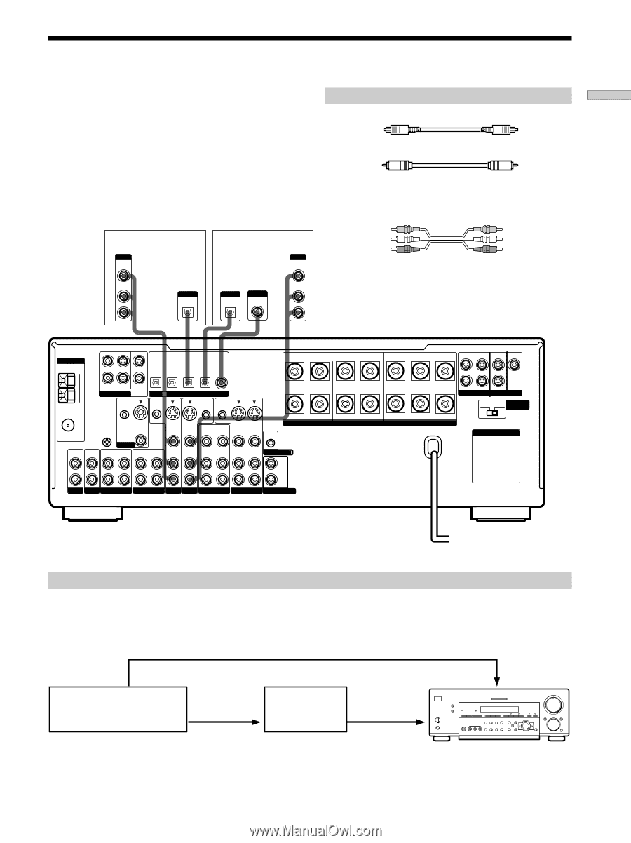
Digital Component Hookups, Optical digital cords not supplied, Audio/video cords not supplied
 |
View all Sony STR-DB840 manuals
Add to My Manuals
Save this manual to your list of manuals |
Page 9 highlights
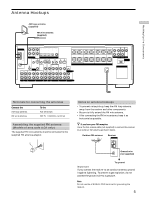
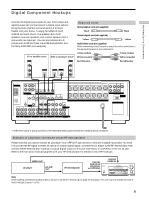
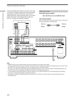
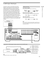
Hooking Up the Components Digital Component Hookups Connect the digital output jacks of your DVD player and satellite tuner (etc.) to the receiver's digital input jacks to bring the multi channel surround sound of a movie theater into your home. To enjoy full effect of multi channel surround sound, five speakers (two front speakers, two rear speakers, and a center speaker) and a sub woofer are required. You can also connect an LD player with an RF OUT jack via an RF demodulator, like the Sony MOD-RF1 (not supplied). TV or satellite tuner OUTPUT VIDEO OUT DVD or LD player (etc.)* OUTPUT VIDEO OUT Required cords Optical digital cords (not supplied) Black Black Coaxial digital cord (not supplied) Yellow Yellow Audio/video cords (not supplied) When connecting a cord, be sure to match the color-coded pins to the appropriate jacks on the components. Yellow (video) Yellow (video) White (L/audio) White (L/audio) Red (R/audio) Red (R/audio) AUDIO OUT L R OUTPUT DIGITAL OPTICAL OUTPUT DIGITAL OPTICAL OUTPUT DIGITAL COAXIAL AUDIO OUT L R ANTENNA AM L MD/DAT MD/DAT TV/SAT DVD/LD DVD/LD OPTICAL OPTICAL OPTICAL OPTICAL COAXIAL OUT IN IN IN IN CENTER B + U FM 75Ω COAXIAL R FRONT REAR SUB WOOFER 5.1CH INPUT CTRL S IN CTRL S STATUS IN DIGITAL CTRL S OUT CTRL S OUT SIGNAL GND U S-VIDEO OUT VIDEO S-VIDEO S-VIDEO IN IN VIDEO VIDEO OUT VIDEO IN VIDEO S-VIDEO S-VIDEO OUT IN VIDEO VIDEO R - IN L MONITOR IN OUT IN OUT IN AUDIO AUDIO IN IN AUDIO AUDIO OUT IN AUDIO OUT AUDIO IN CONTROL A1 L FRONT A REAR CENTER FRONT REAR SUB WOOFER CENTER L L R L R L SPEAKERS IMPEDANCE USE 4 - 16Ω R PRE OUT IMPEDANCE 4 Ω 8 Ω SELECTOR AC OUTLET R PHONO CD MD/DAT TAPE TV/SAT DVD/LD VIDEO 2 VIDEO 1 R 2ND AUDIO OUT * Make either coaxial or optical connections. We recommend making coaxial connections instead of optical connections. Example of LD player connected via an RF demodulator Please note that you cannot connect an LD player's AC-3 RF OUT jack directly to this unit's digital input jacks. You must first convert the RF signal to either an optical or coaxial digital signal. Connect the LD player to the RF demodulator, then connect the RF demodulator's optical or coaxial digital output to this unit's OPTICAL or COAXIAL DVD/LD IN jack. Refer to the instruction manual supplied with your RF Demodulator for details on AC-3 RF hookups. VIDEO OUT LD player AC-3 RF OUT RF demodulator DVD/LD orD(D((C(COVOVOODDDPDPAAITIT//GGLXXLIICCIIDDIITTAAAAAAIILLLLNNLL)))) ?/1 VIDEO IN - + •• • • - + - + - + 4 • • • • 5 • • • 6• • 3 7 2 8 1 0 • • • 9 10 Note When making connections as shown above, be sure to set INPUT MODE (5 on page 27) manually. This unit may not operate correctly if INPUT MODE is set to "AUTO." 9
-
 1
1 -
2
-
3
-
 4
4 -
 5
5 -
 6
6 -
 7
7 -
 8
8 -
 9
9 -
 10
10 -
 11
11 -
 12
12 -
 13
13 -
 14
14 -
15
-
16
-
17
-
18
-
19
-
20
-
21
-
22
-
23
-
24
-
25
-
26
-
27
-
28
-
29
-
30
-
31
-
32
-
33
-
34
-
35
-
36
-
37
-
38
-
39
-
40
-
41
-
42
-
43
-
44
-
45
-
46
-
47
-
48
-
49
-
50
-
51
-
52
-
53
-
54
-
55
-
56
-
57
-
58
-
59
-
60
-
61
-
62
-
63
-
64
 |
 |