Sony STR-K990 Operating Instructions - Page 20
b: Connecting the video components, How to connect your, components, Video input/output jack to
 |
View all Sony STR-K990 manuals
Add to My Manuals
Save this manual to your list of manuals |
Page 20 highlights
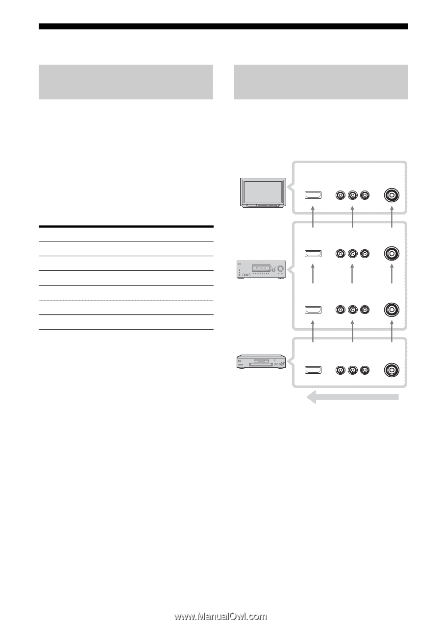
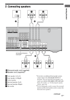
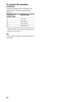
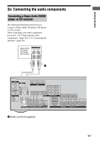
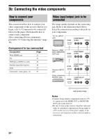
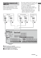
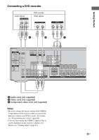
3b: Connecting the video components How to connect your components This section describes how to connect your video components to this receiver. Before you begin, refer to "Component to be connected" below for the pages which describe how to connect each component. After connecting all your components, proceed to "4: Connecting the antennas" (page 28). Component to be connected Component Page With HDMI jack 21 TV 23 DVD player/DVD recorder 24 Satellite tuner/Set-top box 26 VCR 27 Camcorder, video game, etc. 27 Video input/output jack to be connected The image quality depends on the connecting jack. Refer to the illustration that follows. Select the connection according to the jacks on your components. TV, etc. INPUT jack COMPONENT HDMI VIDEO VIDEO Receiver HDMI OUT, MONITOR OUT jack HDMI COMPONENT VIDEO VIDEO ?/1 SPEAKERS (OFF/A/B/A+B) AUTO CAL MIC PHONES VIDEO 3 IN/PORTABLE AV IN VIDEO L AUDIO R DISPLAY INPUT MODE INPUT SELECTOR MASTER VOLUME MEMORY/ TUNING ENTER MODE TUNING 2CH A.F.D. MOVIE MUSIC AUTO CAL MUTING Receiver INPUT jack COMPONENT HDMI VIDEO VIDEO Video component OUTPUT jack HDMI COMPONENT VIDEO VIDEO High quality image Notes • Connect image display components such as a TV or a projector to the HDMI OUT or MONITOR OUT jack on the receiver. • Be sure to turn on the receiver when the video and audio of a playback component are being output to a TV via the receiver. If the power supply of the receiver is not turned on, neither video nor audio is transmitted. 20US
-
 1
1 -
2
-
3
-
4
-
5
-
6
-
7
-
8
-
9
-
10
-
11
-
12
-
13
-
14
-
 15
15 -
 16
16 -
 17
17 -
 18
18 -
 19
19 -
 20
20 -
 21
21 -
 22
22 -
 23
23 -
 24
24 -
 25
25 -
26
-
27
-
28
-
29
-
30
-
31
-
32
-
33
-
34
-
35
-
36
-
37
-
38
-
39
-
40
-
41
-
42
-
43
-
44
-
45
-
46
-
47
-
48
-
49
-
50
-
51
-
52
-
53
-
54
-
55
-
56
-
57
-
58
-
59
-
60
-
61
-
62
-
63
-
64
-
65
-
66
-
67
-
68
-
69
-
70
-
71
-
72
-
73
-
74
-
75
-
76
-
77
-
78
-
79
-
80
 |
 |