Sony XDSPD2000 User Manual (PDBK-202 MPEG Transport Stream Option Board for th - Page 13
Additional Function Menu Settings
 |
View all Sony XDSPD2000 manuals
Add to My Manuals
Save this manual to your list of manuals |
Page 13 highlights
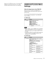
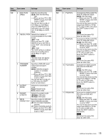
In the case of an XDS Series device, if the sub-item TS MODE of the setup menu item 926 is set to "HDV", metadata other than timecode data is not transmitted. Additional Function Menu Settings When the target device is the PDW-HR1 When this board is installed in the PDW-HR1, the underlined settings in the following tables appear in the function menu. For more information about function menu operations, refer to Chapter 3 "Preparations" in the PDW-HR1 Operation Manual. P1 VIDEO page Item F1: V INPUT Setting Selects the video input signal. HDSDI: HDSDI signal SDSDI: SDSDI signal CMPST: Composite signal i.LINK: i.LINK signal DVB-ASI: DVB-ASI signal SG: Test signal from internal signal generator Notes • When "i.LINK" is selected, HDSDI output and SDSDI output in the PDW-HR1's E-E mode is not guaranteed. DVB-ASI TS signals are not output in the REC mode or E-E mode. • If you select "DVB-ASI", then DVB-ASI TS signals and i.LINK TS signals are not output, regardless of the operating mode of the PDW-HR1. P2 AUDIO page Item Setting F1: AU INPUT Selects the audio input signal to assign to audio channels 1 to 8. SDI: Audio signal embedded into SDI signal ANALOG1: Analog 1 audio signal SG: Test signal from internal signal generator i.LINK: i.LINK signal DVB-ASI: DVB-ASI signal Sub-item F1: A1 INPUT (A5 Input signal of audio INPUT) channel 1 (5) F2: A2 INPUT (A6 Input signal of audio INPUT) channel 2 (6) F3: A3 INPUT (A7 Input signal of audio INPUT) channel 3 (7) F4: A4 INPUT (A8 Input signal of audio INPUT) channel 4 (8) 13 Additional Function Menu Settings
-
 1
1 -
2
-
3
-
4
-
5
-
6
-
7
-
 8
8 -
 9
9 -
 10
10 -
 11
11 -
 12
12 -
 13
13 -
 14
14 -
 15
15 -
 16
16 -
 17
17 -
 18
18 -
19
-
20
-
21
-
22
-
23
-
24
-
25
-
26
-
27
-
28
-
29
-
30
-
31
-
32
-
33
-
34
-
35
-
36
-
37
-
38
-
39
-
40
-
41
-
42
-
43
-
44
-
45
-
46
-
47
-
48
-
49
-
50
-
51
-
52
-
53
-
54
-
55
-
56
-
57
-
58
-
59
-
60
 |
 |