Stihl BR 430 Product Instruction Manual - Page 12
Assembling the Unit - u tube
 |
View all Stihl BR 430 manuals
Add to My Manuals
Save this manual to your list of manuals |
Page 12 highlights
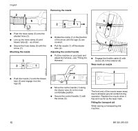
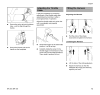
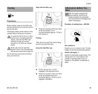
0009BA006 KN English Assembling the Unit The combination wrench and screwdriver are in the supplied accessory bag. BR 350 Blower Tube Fitting the pleated hose on the elbow 1 2 2 3 4 N Push the pleated hose (4) over the slip ring (2) as far as stop. N Position the hose clamp (3) as shown in the illustration. 0009BA002 KN N Ease the slip ring (2) apart and push it over the elbow (1). N Tighten down the screw (arrow). Mounting the blower tubes and nozzle 0009BA027 KN 0009BA004 KN Mounting the control handle 3 7 N Pull the ends of the clamp on the control handle (7) apart and push it over stub of pleated hose (4). N Attach throttle cable to retainer on the hose clamp (3). Adjusting the control handle N Put the machine on your back and adjust the harness - see "Fitting the Harness". 7 5 0009BA003 KN 3 4 N Open the hose clamp (3) and fit it on the pleated hose (4). N Close the hose clamp (3) - engage tab in recess. 5 5 6 N Assemble the blower tubes (5) and nozzle (6). 0009BA005 KN N Push the blower tube (5) into the stub of pleated hose (4) as far as the stop. N Move the control handle (7) along the tube to the most comfortable position. N Tighten down the screw in the control handle (7). 0009BA007 KN 10 BR 350, BR 430
-
 1
1 -
2
-
3
-
4
-
5
-
6
-
 7
7 -
 8
8 -
 9
9 -
 10
10 -
 11
11 -
 12
12 -
 13
13 -
 14
14 -
 15
15 -
 16
16 -
 17
17 -
18
-
19
-
20
-
21
-
22
-
23
-
24
-
25
-
26
-
27
-
28
-
29
-
30
-
31
-
32
-
33
-
34
-
35
-
36
-
37
-
38
-
39
-
40
-
41
-
42
-
43
-
44
-
45
-
46
-
47
-
48
-
49
-
50
-
51
-
52
-
53
-
54
-
55
-
56
-
57
-
58
-
59
-
60
-
61
-
62
-
63
-
64
-
65
-
66
-
67
-
68
-
69
-
70
-
71
-
72
-
73
-
74
-
75
-
76
-
77
-
78
-
79
-
80
-
81
-
82
-
83
-
84
 |
 |
