Stihl BR 600 MAGNUM Product Instruction Manual - Page 13
Assembling the Unit
 |
View all Stihl BR 600 MAGNUM manuals
Add to My Manuals
Save this manual to your list of manuals |
Page 13 highlights
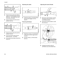
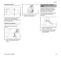
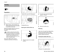
Assembling the Unit Mounting the Control Handle Mounting the Blower Tubes BR 500 1 English Mounting the Hose Clamps and Pleated Hose 31 2 452BA108 KN 452BA095 KN 21 N Pull the two halves of the clamp apart. N Push the control handle (1) onto the blower tube (2). 12 3 N Line up the control handle (1) with the tube's seam - as shown. N Secure the control handle (1) with the screw (3) so that it can still be moved on the blower tube (2). 452BA102 KN 452BA101 KN 2 3 N Depending on your size and reach: Push blower tube (1) up to the appropriate mark on the blower tube (2). N Rotate the blower tube (1) in the direction of the arrow and engage it in the appropriate slot (3). BR 550, BR 600 1 2 3 N Depending on your size and reach: Push blower tube (1) up to the appropriate mark on the blower tube (2). N Rotate the blower tube (1) in the direction of the arrow and engage it in the appropriate slot (3). 452BA096 KN N Push the hose clamp (1) (with retainer for throttle cable) onto the elbow (3) - the positioning marks must face to the left. N Push the pleated hose (2) over the elbow (3). 1 3 2 4 N Push the hose clamp (1) onto the pleated hose (2). N Line up the positioning marks on the hose clamp (1) and elbow (3) - the screw eye faces down. N Secure the hose clamp (1) with the screw (4). 452BA109 KN BR 500, BR 550, BR 600 11
-
 1
1 -
2
-
3
-
4
-
5
-
6
-
7
-
 8
8 -
 9
9 -
 10
10 -
 11
11 -
 12
12 -
 13
13 -
 14
14 -
 15
15 -
 16
16 -
 17
17 -
 18
18 -
19
-
20
-
21
-
22
-
23
-
24
-
25
-
26
-
27
-
28
-
29
-
30
-
31
-
32
-
33
-
34
-
35
-
36
-
37
-
38
-
39
-
40
-
41
-
42
-
43
-
44
-
45
-
46
-
47
-
48
-
49
-
50
-
51
-
52
-
53
-
54
-
55
-
56
-
57
-
58
-
59
-
60
-
61
-
62
-
63
-
64
-
65
-
66
-
67
-
68
-
69
-
70
-
71
-
72
-
73
-
74
-
75
-
76
-
77
-
78
-
79
-
80
-
81
-
82
-
83
-
84
-
85
-
86
-
87
-
88
 |
 |
