TP-Link T2500G-10TSTL-SG3210 T2500G-10TSUN V1 User Guide - Page 143
Application Example for Multicast VLAN
 |
View all TP-Link T2500G-10TSTL-SG3210 manuals
Add to My Manuals
Save this manual to your list of manuals |
Page 143 highlights
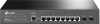
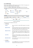
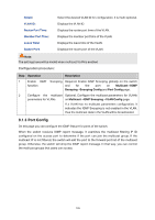
Leave Time: Router Ports: Specify the interval between the switch receiving a leave message from a host, and the switch removing the host from the multicast groups. Enter the static router port which is mainly used in the network with stable topology. Note: 1. The router port should be in the multicast VLAN, otherwise the member ports cannot receive multicast streams. 2. The Multicast VLAN won't take effect unless you first complete the configuration for the corresponding VLAN owning the port on the 802.1Q VLAN page. 3. It is recommended to choose GENERAL as the link type of the member ports in the multicast VLAN. 4. Configure the link type of the router port in the multicast VLAN as TRUNK or configure the egress rule as TAG and the link type as GENERAL otherwise all the member ports in the multicast VLAN cannot receive multicast streams. Configuration procedure: Step Operation Description 1 Enable IGMP Snooping Required. Enable IGMP Snooping globally on the switch function and for the port on Multicast→IGMP Snooping→Snooping Config and Port Config page. 2 Create a multicast VLAN Required. Create a multicast VLAN and add all the member ports and router ports to the VLAN on the VLAN→802.1Q VLAN page. Configure the link type of the member ports as GENERAL. Configure the link type of the router ports as TRUNK or configure the egress rule as tagged GENERAL. 3 Configure parameters for Optional. Enable and configure a multicast VLAN on the multicast VLAN Multicast→IGMP Snooping→Multicast VLAN page. It is recommended to keep the default time parameters. 4 Look over configuration the If it is successfully configured, the VLAN ID of the multicast VLAN will be displayed in the IGMP Snooping Status table on the Multicast→IGMP Snooping→Snooping Config page. Application Example for Multicast VLAN: Network Requirements Multicast source sends multicast streams via the router, and the streams are transmitted to user A and user B through the switch. 133
-
 1
1 -
2
-
3
-
4
-
5
-
6
-
7
-
8
-
9
-
10
-
11
-
12
-
13
-
14
-
15
-
16
-
17
-
18
-
19
-
20
-
21
-
22
-
23
-
24
-
25
-
26
-
27
-
28
-
29
-
30
-
31
-
32
-
33
-
34
-
35
-
36
-
37
-
38
-
39
-
40
-
41
-
42
-
43
-
44
-
45
-
46
-
47
-
48
-
49
-
50
-
51
-
52
-
53
-
54
-
55
-
56
-
57
-
58
-
59
-
60
-
61
-
62
-
63
-
64
-
65
-
66
-
67
-
68
-
69
-
70
-
71
-
72
-
73
-
74
-
75
-
76
-
77
-
78
-
79
-
80
-
81
-
82
-
83
-
84
-
85
-
86
-
87
-
88
-
89
-
90
-
91
-
92
-
93
-
94
-
95
-
96
-
97
-
98
-
99
-
100
-
101
-
102
-
103
-
104
-
105
-
106
-
107
-
108
-
109
-
110
-
111
-
112
-
113
-
114
-
115
-
116
-
117
-
118
-
119
-
120
-
121
-
122
-
123
-
124
-
125
-
126
-
127
-
128
-
129
-
130
-
131
-
132
-
133
-
134
-
135
-
136
-
137
-
 138
138 -
 139
139 -
 140
140 -
 141
141 -
 142
142 -
 143
143 -
 144
144 -
 145
145 -
 146
146 -
 147
147 -
 148
148 -
149
-
150
-
151
-
152
-
153
-
154
-
155
-
156
-
157
-
158
-
159
-
160
-
161
-
162
-
163
-
164
-
165
-
166
-
167
-
168
-
169
-
170
-
171
-
172
-
173
-
174
-
175
-
176
-
177
-
178
-
179
-
180
-
181
-
182
-
183
-
184
-
185
-
186
-
187
-
188
-
189
-
190
-
191
-
192
-
193
-
194
-
195
-
196
-
197
-
198
-
199
-
200
-
201
-
202
-
203
-
204
-
205
-
206
-
207
-
208
-
209
-
210
-
211
-
212
-
213
-
214
-
215
-
216
-
217
-
218
-
219
-
220
-
221
-
222
-
223
-
224
-
225
-
226
-
227
-
228
-
229
-
230
-
231
-
232
-
233
-
234
-
235
-
236
-
237
-
238
-
239
-
240
-
241
-
242
-
243
-
244
-
245
-
246
-
247
-
248
-
249
-
250
-
251
-
252
-
253
-
254
-
255
-
256
-
257
-
258
-
259
-
260
-
261
-
262
-
263
-
264
-
265
-
266
-
267
-
268
-
269
-
270
-
271
-
272
-
273
-
274
-
275
-
276
-
277
-
278
-
279
-
280
-
281
-
282
-
283
-
284
-
285
-
286
 |
 |
