TP-Link TL-SL2428 TL-SL2428 V1 User Guide - Page 104
Schedule Mode, 9.2 Bandwidth Control
 |
View all TP-Link TL-SL2428 manuals
Add to My Manuals
Save this manual to your list of manuals |
Page 104 highlights
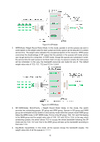
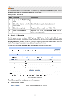
3 Map the DSCP priority to the Required. Select DSCP priority and the corresponding priority level priority level. 4 Select a schedule mode Required. Log on to the Schedule Mode page to select a schedule mode. 9.1.4 Schedule Mode On this page you can select a schedule mode for the switch. When the network is congested, the problem that many packets compete for resources must be solved, usually in the way of queue scheduling. The switch will control the forwarding sequence of the packets according to the priority queues and scheduling algorithms you set. On this switch, the priority levels are labeled as TC0, TC1... TC3. Choose the menu QoS→DiffServ→Schedule Mode to load the following page. Figure 9-9 Schedule Mode The following entries are displayed on this screen: Schedule Mode Config SP-Mode: Strict-Priority Mode. In this mode, the queue with higher priority will occupy the whole bandwidth. Packets in the queue with lower priority are sent only when the queue with higher priority is empty. WRR-Mode: Weight Round Robin Mode. In this mode, packets in all the queues are sent in order based on the weight value for each queue. The weight value ratio of TC0, TC1, TC2 and TC3 is 1:2:4:8. SP+WRR-Mode: Strict-Priority + Weight Round Robin Mode. In this mode, this switch provides two scheduling groups, SP group and WRR group. Queues in SP group and WRR group are scheduled strictly based on strict-priority mode while the queues inside WRR group follow the WRR mode. In SP+WRR mode, TC3 is in the SP group; TC0, TC1 and TC2 belong to the WRR group and the weight value ratio of TC0, TC1 and TC2 is 1:2:4. In this way, when scheduling queues, the switch allows TC3 to occupy the whole bandwidth following the SP mode and the TC0, TC1 and TC2 in the WRR group will take up the bandwidth according to their ratio 1:2:4. Equ-Mode: Equal-Mode. In this mode, all the queues occupy the bandwidth equally. The weight value ratio of all the queues is 1:1:1:1. 9.2 Bandwidth Control Bandwidth function, allowing you to control the traffic rate and broadcast flow on each port to ensure network in working order, can be implemented on Rate Limit and Storm Control pages. 97
-
 1
1 -
2
-
3
-
4
-
5
-
6
-
7
-
8
-
9
-
10
-
11
-
12
-
13
-
14
-
15
-
16
-
17
-
18
-
19
-
20
-
21
-
22
-
23
-
24
-
25
-
26
-
27
-
28
-
29
-
30
-
31
-
32
-
33
-
34
-
35
-
36
-
37
-
38
-
39
-
40
-
41
-
42
-
43
-
44
-
45
-
46
-
47
-
48
-
49
-
50
-
51
-
52
-
53
-
54
-
55
-
56
-
57
-
58
-
59
-
60
-
61
-
62
-
63
-
64
-
65
-
66
-
67
-
68
-
69
-
70
-
71
-
72
-
73
-
74
-
75
-
76
-
77
-
78
-
79
-
80
-
81
-
82
-
83
-
84
-
85
-
86
-
87
-
88
-
89
-
90
-
91
-
92
-
93
-
94
-
95
-
96
-
97
-
98
-
 99
99 -
 100
100 -
 101
101 -
 102
102 -
 103
103 -
 104
104 -
 105
105 -
 106
106 -
 107
107 -
 108
108 -
 109
109 -
110
-
111
-
112
-
113
-
114
-
115
-
116
-
117
-
118
-
119
-
120
-
121
-
122
-
123
-
124
-
125
-
126
-
127
-
128
-
129
-
130
-
131
-
132
-
133
-
134
-
135
-
136
-
137
-
138
-
139
-
140
 |
 |