Tanaka SF-MC Mini Cultivator Attachment Manual - Page 3
Awarning
 |
View all Tanaka SF-MC Mini Cultivator Attachment manuals
Add to My Manuals
Save this manual to your list of manuals |
Page 3 highlights
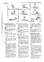
SF•PE 1 \ 0 , / 1 1 -3 4 2 Fig. 3-1 ti t t Fig. 3-3 oC 7 t \ _ Fig. 4-1 I ( 0 Fig. 5-1 ----- 2 ; a - ., 4 ( 2 Fig. 3-2 L.H. 3 Fig. 3-4 1 Fig. 4-2 Fig. 4-3 0 ( Fig. 5-2 63. Assembly procedures Installation of blade guard (Fig.3-1) 1) Install blade guard (1) on gearcase (4) temporarily by clamping with guard brackets (2) and screws (3). Then tighten as needed. 2) Line up the slot of guard bracket (2) with the same of gearcase (4), then tighten screws (3) securely. (Fig.3-2) Installation of wheel (Fig.3-3) 1) Installation the wheel as the illustra- tion. 2) After installation, check if the wheel turns smoothly. Installation of blade (Fig.3-4) 1) Before installation of blade, take off left-hand threaded fixing nut (1), cutter holder cap (2) from the blade shaft. 2) Install blade (3) on the shaft and then replace the cutter holder cap and fixing nut in order. NOTE! When installing cutter holder cap (2), be sure to set concave side facing blade. 3) Insert the locking bar (4) into the hole of the cutter holder (5) and gearcase by lining up each hole. 4) Tighten the fixing nut securely (clockwise to loosen/counter-clockwise to tighten.) 4. Operating Procedures Cutting (Fig.4-1, 4-2) Use edger properly. Use only for edging the type of grass and other growth for which the machine is designed. Do not abuse engine. 1) Adjust cutting depth by loosening knob nut (1) and moving location of wheel up or down. To increase cutting depth, move the wheel location upwards and to decrease, move it lower. After the location is decided, tighten knob nut (1) securely. NOTE! The adjustment should be made after engine stopped completely and stop switch is in stop position. 2) Always hold unit firmly with both hands and keep your body well balanced. 3) Always operate the power edger positioned at the right-side of the operator. (Fig.4-3) ,LWARNING! Operate the unit from position where guards block the line of sight to the cutting blade. ZWARNING! If cutter should strike against stones or other debris, stop the engine and make sure that the cutter and related parts are undamaged. When grass or vines wrap around cutter, stop engine and blade and remove it. 5. Maintenance Blade (1) (Fig.5.1) AWARNING! Wear protective gloves when handling or performing maintenance on the blade. • When replacing blade, purchase one recommended by TANAKA, with a 25.4mm (one inch) fitting hole. • Use correct blade for the type of work. • When replacing blade, use appropriate tools. • Discard blades that are bent, warped, cracked, broken or damaged in any way. Angle transmission (Fig.5-2) Check angle transmission or angle gear for grease level about every 50 hours of operation by removing the grease filler plug on the side of angle transmission. If no grease can be seen on the flanks of the gears, fill the transmission with •a quality lithium based multipurpose grease up to 3/4. Do not completely fill the transmission. Maintenance schedule Below you will find some general maintenance instructions. For further information please contact your service dealer. Daily maintenance • Clean the exterior of the unit. • Check the blade guard for damage or cracks. Change the guard in case of impacts or cracks. • Check that the cutting attachment is properly centred, sharp, and without cracks. An offcentred cutting attachment induces heavy vibrations that may damage the unit. • Check that the cutting attachment nut is sufficiently tightened. • Check that the nuts and screws are sufficiently tightened. Weekly maintenance • Check the starter, especially cord and return spring. • Clean the exterior of the spark plug. • Remove it and check the electrode gap. Adjust it to 0.6mm, or change the spark plug. • Clean the cooling fins on the cylinder and check that the air intake at the starter is not clogged. • Check that the angle gear is filled with grease up to 3/4. • Clean the air filter. Monthly maintenance • Rinse the fuel tank with gasoline. • Clean the exterior of the carburetor and the space around it. • Clean the fan and the space around it. 03. Procedes d'assemblage Installation de la garde de lame (Fig. 3-1) 1) Montage du protecteur de lame (1) sur la boite d'engrenages (4) temporairement en le bloquant au moyen des supports protecteurs (2) et des vis (3). 2)Aligner les rainures du support protecteur (2) a celles de la boTte d'engrenages (4) et, ensuite, serrer fermement les vis (3). (Fig. 3-2) Installation de la route (Fig. 3-3) 1) Monter la roue conformement ('illustration. 2) Faire la verification apres le montage pour voir si la roue tourne comme it fault. Installation de la lame (Fig. 3-4) 1) Avant d'installer la lame, retirer l'ecrou de fixation a filet a gauche (1) et le capuchon de fixation de la lame (2) places sur I'arbre de la lame. 2) Installer la lame (3) sur l'arbre et remonter le capuchon de fixation de la lame et l'ecrou dans cet ordre. REMARQUE! Lors de ( 'installation de capuchon de fixation (2), veiller a place la face concave en face de la lame. 3) Inserer la barre de verouillage (4) dans ('orifice du dispositif de fixation de la lame (5) et du carter d'engrenages en alignant cheque ouverture. 4) Resserrer solidement l'ecrou de fixation (dans le sens des aiguilles d'une montre pour desserrer, et dans le sens contraire pour serrer). 4. Procedes de fonctionnement Coupage (Fig. 4-1, 4-2) Employer le tranche-gazon comme it faut. L'employer seulement pour la delignure du type d'herbe et d'autres pousses pour lesquels la machine a ete congue. Ne pas abuser du moteur. 1) Adjuster la profondeur du coupage en desserrant l'ecrou de reglade (1) et en deplacant I'endroit de la roue vers le haut ou vers le bas. Deplacer I'endroit de la route vers le haut pour augmenter la profondeur du coupage, tandis que deplacerle vers le bas pour la reduire. Apres avoir trouve I'endroit juste, serrer fermement l'ecrou de reglage (1).
-
 1
1 -
 2
2 -
 3
3 -
 4
4 -
 5
5 -
 6
6 -
 7
7 -
 8
8
 |
 |
