Tanaka TCG27EBSP Owner's Manual - Page 8
Assembly Procedures
 |
View all Tanaka TCG27EBSP manuals
Add to My Manuals
Save this manual to your list of manuals |
Page 8 highlights
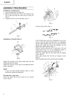
English ASSEMBLY PROCEDURES 4 Installation of attachment 1. Join the attachment in place of it. 2. Make sure the lock pin (1) fits in the location hole (2) of tube and that the tube will not come off. (Fig. 1) 3. Tighten the knob nut (3) securely. (Fig. 1) 1 3 2 Fig. 3 Connect stop cords. (Fig. 4) Fig. 1 Installation of handle (Fig. 2) Fig. 2 Attach the handle to the drive shaft tube with the angle towards the engine. Adjust the location to the most comfortable position before operation. Fig. 4 If the throttle outer end (5) is threaded on your unit, screw it and the earth terminal (6) (if so equipped) into the cable adjuster stay (7) all the way, and then tighten this cable end using the adjuster nut (8) against the cable adjuster stay (7). Connect throttle wire end (9) to carburetor (10) and install swivel cap (11) (if so equipped) where is included in tool bag, onto swivel (10) (Fig. 5). Press the upper tab (4) and close the air cleaner cover. (Fig. 3) Store stop cords (12) into the air cleaner cover. (Fig. 6) Some models may come with the parts installed. 7 6 10 11 5 NOTE If your unit has handle location label on drive shaft tube, follow the illustration. 9 Throttle wire / stop cord Press the upper tab (4) and open the air cleaner cover. (Fig. 3) 8 Fig. 5 8
-
 1
1 -
2
-
 3
3 -
 4
4 -
 5
5 -
 6
6 -
 7
7 -
 8
8 -
 9
9 -
 10
10 -
 11
11 -
 12
12 -
 13
13 -
14
-
15
-
16
-
17
-
18
-
19
-
20
-
21
-
22
-
23
-
24
-
25
-
26
-
27
-
28
-
29
-
30
-
31
-
32
-
33
-
34
-
35
-
36
-
37
-
38
-
39
-
40
-
41
-
42
-
43
-
44
-
45
-
46
-
47
-
48
-
49
-
50
-
51
-
52
-
53
-
54
-
55
-
56
 |
 |
