Tanaka TCG27EBSP Owner's Manual - Page 9
may occur.
 |
View all Tanaka TCG27EBSP manuals
Add to My Manuals
Save this manual to your list of manuals |
Page 9 highlights
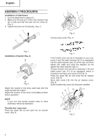
English 12 CAUTION Some cutting attachment guards are equipped with sharp line limiters. Be careful with handling it. NOTE If your unit has guard location label on drive shaft tube, follow the indication. Installation of semi-auto cutting head Fig. 6 Installation of cutting attachment guard (Fig. 7) WARNING ● Do not start or operate unit unless each guard is properly assembled to unit. ● lf unit is operated without a sharp line limiters, the line will become too long, the engine will overheat, and engine damage may occur. ● Check sharp line limiters surely cut nylon line when operating. WARNING If an incorrect or faulty guard is fitted, this may cause serious personal injury. 1. Function Automatically feeds more nylon cutting line when it is tapped at low rpm (not greater than 4,500 min-1). Specifications Type of Code No. attaching screw Direction of rotation 6696454 Female 6698639 screw Counterclockwise Size of attaching screw M10×P1.25LH Applicable nylon cord Cord diameter: 3/32˝ (Φ2.4 mm) Length: 13 ft (4 m) 2. Precautions ○ The case must be securely attached to the cover. ○ Check the cover, case and other components for cracks or other damage. ○ Check the case and button for wear. If the wear limit mark (13) on the case is no longer visible or there is a hole in the bottom (14) of the button, change the new parts immediately. (Fig. 8) 13 14 Fig. 7 NOTE The guard bracket may come already mounted to the gear case on some models. Install the cutting attachment guard on drive shaft tube against angle transmission. Tighten the guard bracket firmly so that the cutting attachment guard does not swing or move down during operation. Install the cutting attachment guard to the guard bracket, which also secures the guard to the gear case using the two guard mounting screws. Fig. 8 ○ The cutting head must be securely mounted to the unit's gear case. ○ For outstanding performance and reliability, always use Tanaka nylon cutting line. Never use wire or other materials that could become a dangerous projectile. 9
-
 1
1 -
2
-
3
-
 4
4 -
 5
5 -
 6
6 -
 7
7 -
 8
8 -
 9
9 -
 10
10 -
 11
11 -
 12
12 -
 13
13 -
 14
14 -
15
-
16
-
17
-
18
-
19
-
20
-
21
-
22
-
23
-
24
-
25
-
26
-
27
-
28
-
29
-
30
-
31
-
32
-
33
-
34
-
35
-
36
-
37
-
38
-
39
-
40
-
41
-
42
-
43
-
44
-
45
-
46
-
47
-
48
-
49
-
50
-
51
-
52
-
53
-
54
-
55
-
56
 |
 |
