Thermador PCG366G Installation Instructions PART3 - Page 10
/4 To Centerline - installation
 |
View all Thermador PCG366G manuals
Add to My Manuals
Save this manual to your list of manuals |
Page 10 highlights
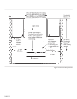
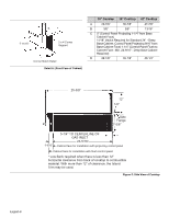
7-11/16" C B 2 x 4 Corner Support Corner Notch Detail Detail A: (Front Face of Cabinet) 30" Cooktop 36" Cooktop 48" Cooktop A 29-7/8" 35-7/8" 47-7/8" B 3/8" 3/8" 13/16" C 0" (Control Panel Projecting 1-1/4" from Base Cabinet Face) 11/16" (Notch Required for Standard 24" - Deep Base Cabinet, Control Panel Projecting 9/16" from Base Cabinet Face) 1-1/4" (Control Panel Flush to Cabinet Face - Min. 24-9/16" - Deep Base Cabinet Required) D 29-1/8" 35-1/8" 46-1/4" 25-3/8" 12" 1/2" Side Flange 7-5/8" 1-1/4" 5-1/4" TO CENTERLINE OF GAS INLET 23-5/16" Cabinet face for installation with projecting control panel Cabinet face for installation with flush control panel * Low Back required when there is less than 12" horizontal clearance from back of cooktop to combustible material. With more than 12" of clearance, the Island Trim may be used. Figure 5: Side View of Cooktop English 8
-
 1
1 -
2
-
3
-
4
-
 5
5 -
 6
6 -
 7
7 -
 8
8 -
 9
9 -
 10
10 -
 11
11 -
 12
12 -
 13
13 -
 14
14 -
 15
15 -
16
-
17
-
18
-
19
-
20
-
21
-
22
-
23
-
24
-
25
-
26
-
27
-
28
-
29
-
30
-
31
-
32
-
33
-
34
-
35
-
36
-
37
-
38
-
39
-
40
-
41
-
42
-
43
-
44
-
45
-
46
-
47
-
48
-
49
-
50
-
51
-
52
-
53
-
54
-
55
-
56
 |
 |
