Thermador PCG486GD Installation Instructions PART3 - Page 12
Step 3: Unpacking, Moving, Placing and, Anchoring the Cooktop - parts
 |
View all Thermador PCG486GD manuals
Add to My Manuals
Save this manual to your list of manuals |
Page 12 highlights
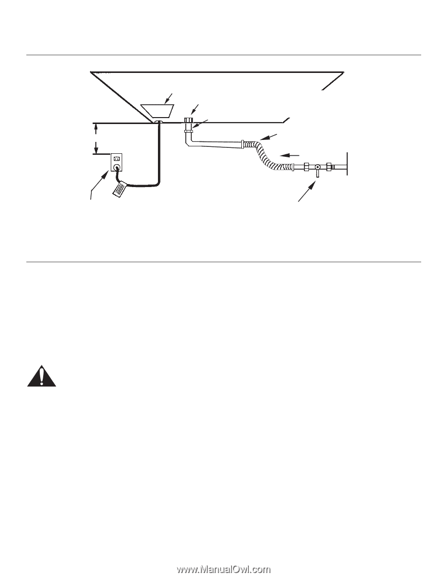
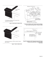
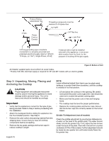
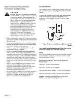
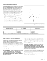
Product Rating Label/Serial Tag 3" Min. Power Cord or Conduit Threading compounds must be resistant to Propane Gas 1/2" NPT 3/4" flex line gas flow 3-Prong grounding type receptacle connected to a properly grounded and polarized electrical supply rated at 120VAC, 10 Amps, (or 15A*) Single Phase, 60 HZ. A manual valve must be installed external to the appliance, in an accessible location from the front, for the purpose of shutting off the gas supply. Figure 9: Bottom of Unit All Installer supplied parts must conform to Local Codes. *15 Amp 120 VAC electrical supply is required for 36" and 48" models with an electric griddle. Step 3: Unpacking, Moving, Placing and Anchoring the Cooktop CAUTION Proper equipment and adequate manpower must be used in moving the appliance to avoid damage and/or personal injury. The unit is heavy and should be handled accordingly. Important • Verify that the appliance is correct for the type of gas being provided. Refer to Step 4 before proceeding with the installation. • Attach the backguard before sliding the appliance into the final installed position. See Step 6. • Remove the outer carton and packing material from the shipping base. Ensure that you have all cooktop components before proceeding. • Remove the top grate castings and burner caps to reduce cooktop's weight. NOTE: Leave adhesive-backed foam layer over brushed-metal surfaces, to protect finish from scratches, until the cooktop is installed in its final position. • Lift and place the cooktop in the opening. Be careful not to pinch the power cord or gas inlet. Care should be used not to scratch the griddle cooking plate. • Make sure that the power cord is free and hanging loose. • The cooktop must be level for proper performance. • Replace the cooking grates and burner caps. Ensure that the burner caps are correctly seated on the burner bases. Griddle Tilt Adjustment (not all models) Check the griddle adjustment by pouring two tablespoons of water on the back of the griddle plate. The water should slowly roll into the grease tray. If not, adjust the two screws under the back of the plate. Start with one half turn counterclockwise (CCW) of the screws. Further adjustment should be made by one-quarter turn until water slowly flows into the grease tray. English 10
-
 1
1 -
2
-
3
-
4
-
5
-
6
-
 7
7 -
 8
8 -
 9
9 -
 10
10 -
 11
11 -
 12
12 -
 13
13 -
 14
14 -
 15
15 -
 16
16 -
 17
17 -
18
-
19
-
20
-
21
-
22
-
23
-
24
-
25
-
26
-
27
-
28
-
29
-
30
-
31
-
32
-
33
-
34
-
35
-
36
-
37
-
38
-
39
-
40
-
41
-
42
-
43
-
44
-
45
-
46
-
47
-
48
-
49
-
50
-
51
-
52
-
53
-
54
-
55
-
56
 |
 |