Thermador SGSX365TS Installation instructions - Page 11
Connect Electrical Supply, Burner Cap Placement
 |
View all Thermador SGSX365TS manuals
Add to My Manuals
Save this manual to your list of manuals |
Page 11 highlights
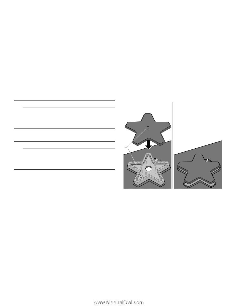
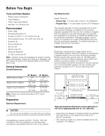
Important Notes for Gas Connection: Burner Cap Placement ▯ The appliance and its individual gas shutoff valve must be disconnected from the gas supply piping system during any pressure testing of that system at test pressures in excess of 1/2 psi (3.5kPa). ▯ The appliance must be isolated from the gas supply piping system by closing its individual manual shut-off valve during any pressure testing of the gas supply piping system at test pressures equal to or less than 1/2 psi (3.5kPa). Connect Electrical Supply Before connecting the 5-foot (1.5m) supply cord to a wall receptacle, make certain that gas shut-off valve and all burner controls are in OFF position. Burner Cap Placement 9 WARNING ▯ Each cap has a letter (B, D or F) cast in the underside of the cap that corresponds to a letter (B, D or F) cast in the burner base that is attached to the appliance. ▯ After electrical connection is complete, place each burner base on the corresponding location on the cooktop. One of the three bars on the burner base should line up with the notch and prevent the base from rotating. The small hole or cutout near the edge should also line up with the igniter. See Illustration below. ▯ Once each base is located and resting evenly, place each burner cap on its correct burner base. See Illustration below. ▯ Place burner cap gently on top of base so that the prongs of the burner base fit snugly into the groove of the burner cap. 1 2 To prevent flare-ups, do not use the cooktop without all burner caps and all burner grates properly positioned. ' 9 WARNING To prevent burns, do not touch burner caps or grates while hot. Turn the cooktop off and allow the burners to cool. Do not attempt any adjustment of the pressure regulator, except conversion to propane. The burner caps must be properly placed for the cooktop to function properly. If the burner cap is not properly placed, one or more of the following problems may occur: ▯ Burner flames are too high. ▯ Flames shoot out of burners. ▯ Stainless steel discolors. ▯ Burners do not ignite. ▯ Burner flames light unevenly. ▯ Burner emits gas odor. ' Placing Burner Caps 11
-
 1
1 -
2
-
3
-
4
-
5
-
 6
6 -
 7
7 -
 8
8 -
 9
9 -
 10
10 -
 11
11 -
 12
12 -
 13
13 -
 14
14 -
 15
15 -
 16
16 -
17
-
18
-
19
-
20
-
21
-
22
-
23
-
24
-
25
-
26
-
27
-
28
-
29
-
30
-
31
-
32
-
33
-
34
-
35
-
36
-
37
-
38
-
39
-
40
-
41
-
42
-
43
-
44
 |
 |