Thermador VCIN36JP Installation Instructions - Page 23
Installation, Procedure
 |
View all Thermador VCIN36JP manuals
Add to My Manuals
Save this manual to your list of manuals |
Page 23 highlights
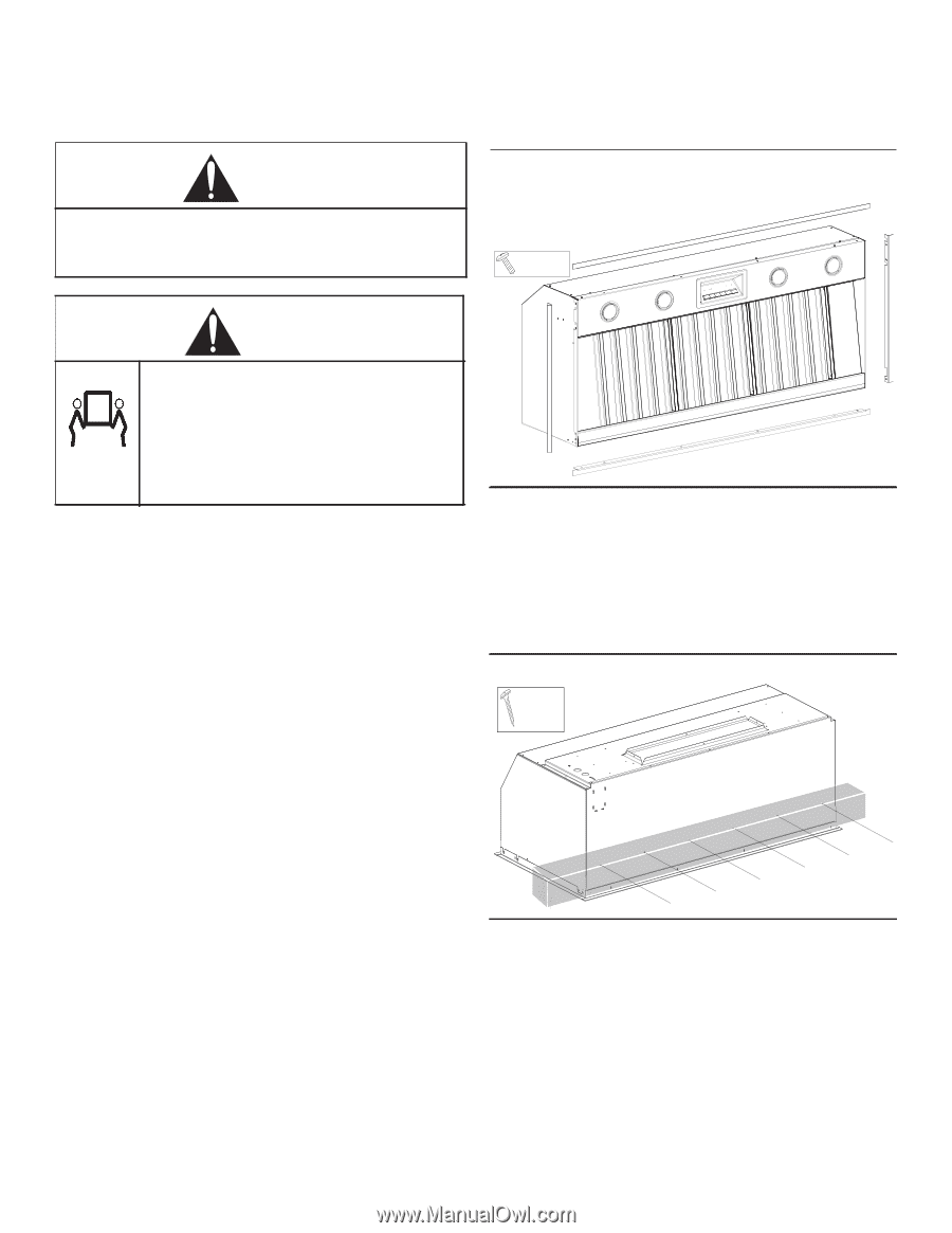
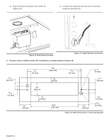
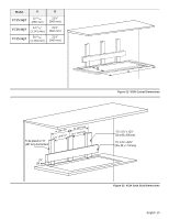
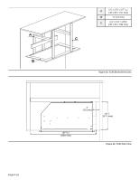
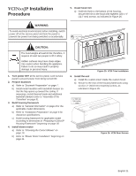
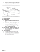
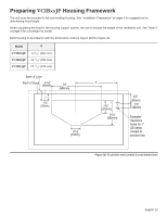
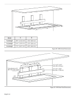
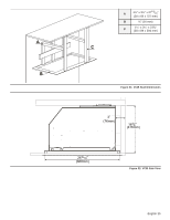
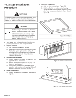
VCINxxJP Installation Procedure 5. Install hood trim a) Hold trim flush to the bottom of the housing. Secure the trim to the hood with eighteen (18) x ½" (12.7 mm) screws, as indicated in Figure 25. WARNING: To avoid electrical shock hazard, before installing, switch power off at the service panel and lock the panel to prevent the power from being switched on accidentally. ½" (12.7 mm) x18 CAUTION: The hood weighs at least 60 lbs; therefore, it requires at least two people to lift it safely. Hidden surfaces may have sharp edges. Use caution when handling the appliance. Failure to do so may result in property damage or personal injury. 1. Turn power OFF at the service panel. Lock service panel to prevent power from being turned ON. 2. Prepare ductwork a) Refer to "Ductwork Preparation" on page 7. b) Install metal transition with backdraft damper so that the flap opens up toward the ceiling. If necessary, install thermal break and additional backdraft damper (refer to "Assembly of the Transition" on page 9). 3. Build housing framework a) Refer to "General Information" on page 4 for the applicable model dimensions. b) Refer to "Installation Preparation" on page 6 for clearance specifications. c) Build housing framework for applicable model according to dimensions in "Preparing VCINxxJP Housing Framework" beginning on page 18. 4. Install blower motor a) Refer to "Choosing the Correct Blower" on page 10. b) Refer to "Blower Motor Installation" beginning on page 11. Figure 25: VCIN Trim Installation 6. Install the unit a) Install the custom insert inside the custom hood. b) Secure to the rear of the housing framework using six (6) x 2" (50.8 mm) mounting screws, as indicated in Figure 26. 2" (50.8 mm) X6 mounting screws Figure 26: VCIN Rear Screws English 21
-
 1
1 -
2
-
3
-
4
-
5
-
6
-
7
-
8
-
9
-
10
-
11
-
12
-
13
-
14
-
15
-
16
-
17
-
 18
18 -
 19
19 -
 20
20 -
 21
21 -
 22
22 -
 23
23 -
 24
24 -
 25
25 -
 26
26 -
 27
27 -
 28
28 -
29
-
30
-
31
-
32
-
33
-
34
-
35
-
36
-
37
-
38
-
39
-
40
-
41
-
42
-
43
-
44
-
45
-
46
-
47
-
48
-
49
-
50
-
51
-
52
-
53
-
54
-
55
-
56
-
57
-
58
-
59
-
60
-
61
-
62
-
63
-
64
-
65
-
66
-
67
-
68
-
69
-
70
-
71
-
72
-
73
-
74
-
75
-
76
-
77
-
78
-
79
-
80
-
81
-
82
-
83
-
84
-
85
-
86
-
87
-
88
-
89
-
90
-
91
-
92
-
93
-
94
-
95
-
96
 |
 |