Thermador VCIN36JP Installation Instructions - Page 25
VCIBxxJP - vcib36jp installation
 |
View all Thermador VCIN36JP manuals
Add to My Manuals
Save this manual to your list of manuals |
Page 25 highlights
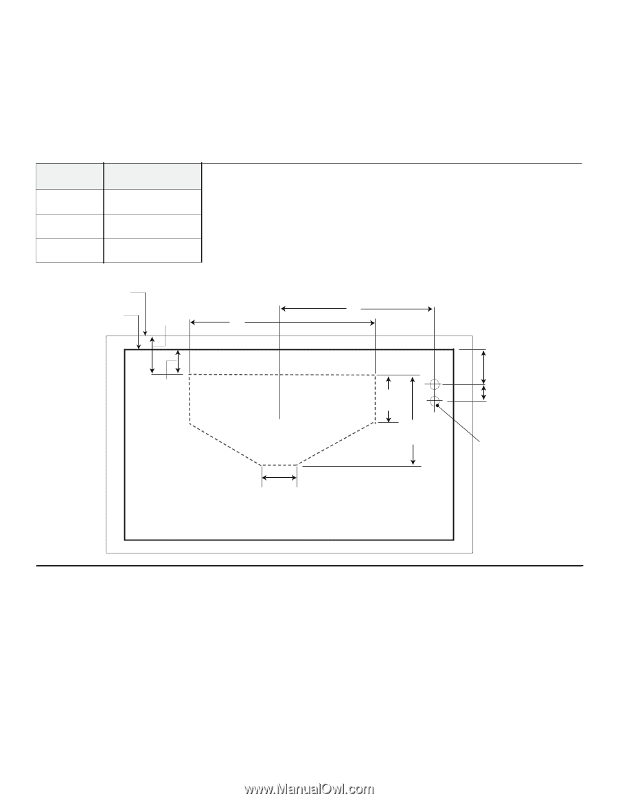
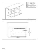
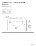
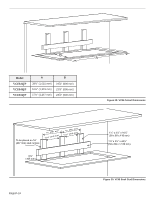
Preparing VCIBxxJP Housing Framework The unit must be mounted to the surrounding housing. See "Installation Preparation" on page 6 for suggestions for determining hood height. When calculating the load for the housing support system, be sure to include the weight of the ventilation unit. See Table 3 on page 6 for unit weight by model. Build housing in accordance with the dimensions noted in Figure 28 thru Figure 32. Model A VCIB36JP VCIB48JP VCIB54JP 14 3/16" (360 mm) 19 13/16" (503 mm) 22 13/16" (579 mm) Back of Liner Back of Hood 3 3/16" (81mm) 23" (584mm) 11/8" (29mm) 33/16" (81mm) A 77/8" (200mm) 10¼" (260mm) 23/8" (86mm) 17/8" (48mm) Diameter clearance holes for 1" (25.4mm) conduit to junction box Figure 28: Transition and Conduit Cutout Dimensions English 23
-
 1
1 -
2
-
3
-
4
-
5
-
6
-
7
-
8
-
9
-
10
-
11
-
12
-
13
-
14
-
15
-
16
-
17
-
18
-
19
-
 20
20 -
 21
21 -
 22
22 -
 23
23 -
 24
24 -
 25
25 -
 26
26 -
 27
27 -
 28
28 -
 29
29 -
 30
30 -
31
-
32
-
33
-
34
-
35
-
36
-
37
-
38
-
39
-
40
-
41
-
42
-
43
-
44
-
45
-
46
-
47
-
48
-
49
-
50
-
51
-
52
-
53
-
54
-
55
-
56
-
57
-
58
-
59
-
60
-
61
-
62
-
63
-
64
-
65
-
66
-
67
-
68
-
69
-
70
-
71
-
72
-
73
-
74
-
75
-
76
-
77
-
78
-
79
-
80
-
81
-
82
-
83
-
84
-
85
-
86
-
87
-
88
-
89
-
90
-
91
-
92
-
93
-
94
-
95
-
96
 |
 |