Toro 20351 Quality Guide - Page 20
Checking and Adjusting, Blade Tracking, Adjusting Blade Level
 |
View all Toro 20351 manuals
Add to My Manuals
Save this manual to your list of manuals |
Page 20 highlights
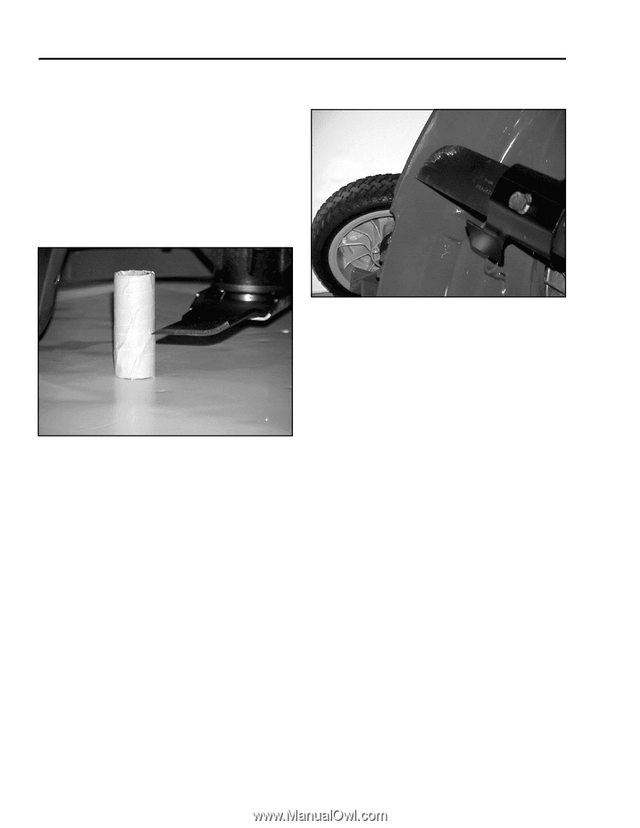
Checking and Adjusting the Blade Level If you don't have the measuring tool, use a piece of wood just short enough to fit under the mower housing. Wrap one end with tape. Place the untaped end on the floor and the tape against the cutting edge of the blade (Figure 17). Make a mark in the tape with the blade. Measure from the end that was on the floor to the mark you made in the tape and record the measurement on your sketch. Cover the marked tape with a fresh piece of tape. Repeat this process for each measurement, adding another layer of tape after each measurement so you have only one mark each time you measure. engine or spindle and the housing. Check for level after installing shims. Figure 18 MVC-716X.JPG Riding Mowers For instructions on checking and adjusting the blade tracking on a riding mower, see the subsection in these instructions that covers the mower on which you are working. Figure 17 MVC-729X.JPG 6. When the measurements are complete, proceed to the subsections in these instructions that cover the blade tracking and blade leveling procedures for the mower on which you are working. Checking and Adjusting Blade Tracking Walk Behind Mowers Blade tracking can generally be checked visually. Use one blade tip turning it one rotation. It should stay close to the same level all the way around, a minimum of approximately 1/8 inch (3.1mm) above the bottom edge (Figure 18) of the mower housing. (Housings with cut-outs are more difficult to check. Verify all other measurements when checking these mowers.) If there is a large difference in the measurement from one area to another, the mower housing may be bent at the point where the engine or blade spindle mounts. You can correct for this by placing shim washers between the Adjusting Blade Level Walk Behind Mowers Specifications and Tolerances On walk behind mowers the blade should be level side-to-side within 1/8 inch (3.1mm). The mower is designed with a 1-degree downward blade pitch when the tips of the blade are at the 12 o'clock and 6 o'clock positions from the operator's position. The difference between the measurement at the front and the rear will vary with the blade length. See the following table for common measurements. Note: Tolerances in everything including wheels and pivot arms make the blade pitch specification approximate. Although the blade should not be level front to rear, it should not be tilted excessively. If the front-to-rear difference is within 1/8 inch (3.1mm) of the specification, the pitch is acceptable. 4 - 4 Service Dealer's Guide to Great Quality of Cut
-
 1
1 -
2
-
3
-
4
-
5
-
6
-
7
-
8
-
9
-
10
-
11
-
12
-
13
-
14
-
 15
15 -
 16
16 -
 17
17 -
 18
18 -
 19
19 -
 20
20 -
 21
21 -
 22
22 -
 23
23 -
 24
24 -
 25
25 -
26
-
27
-
28
-
29
-
30
-
31
-
32
-
33
-
34
-
35
-
36
-
37
-
38
-
39
-
40
-
41
-
42
-
43
-
44
-
45
-
46
-
47
-
48
-
49
-
50
-
51
-
52
-
53
-
54
-
55
-
56
-
57
 |
 |