Toshiba 36AFX61 Owners Manual - Page 8
Two VCRs
 |
View all Toshiba 36AFX61 manuals
Add to My Manuals
Save this manual to your list of manuals |
Page 8 highlights
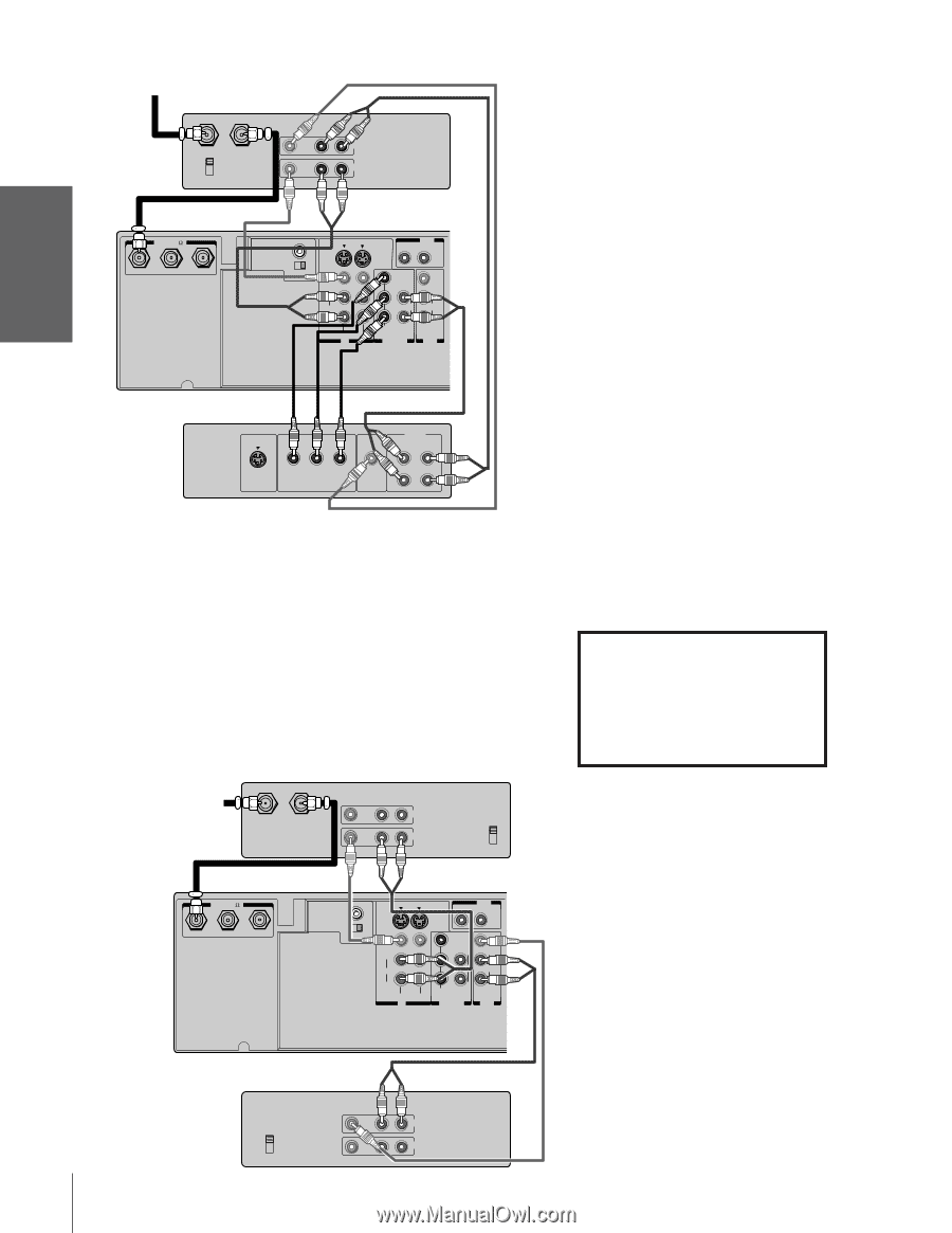
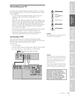
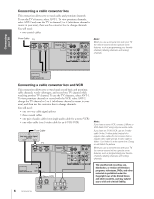
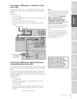
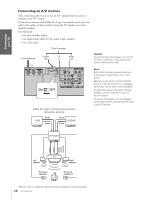
Introduction Connecting your TV Using the Remote Control (Continued from previous page) From Antenna Stereo VCR IN from ANT OUT to TV CH 3 CH 4 VIDEO AUDIO L R IN OUT TV ANT( 75 ) ANT-1 OUT ANT- 2 AUDIO CENTER CHANNEL IN ON S-VIDEO OUT R L VAR AUDIO OFF VIDEO Y L/ MONO CB L AUDIO CR AUDIO R R COLOR VIDEO 1 VIDEO 2 STREAM IN DVD IN VIDEO L/ MONO AUDIO R OUT Satelite IN Y CB CR S-VIDEO COMPONENT VIDEO VIDEO OUT AUDIO OUT L L R R DVD Player with ColorStream™ Note: For the highest possible picture quality, you must use the ColorStream (component video) connections between the TV and DVD player. Connect the ColorStream cables from the DVD player to the jacks marked "ColorStream" on the TV. The ColorStream input on the TV is for use with DVD players that offer interlaced (480i) scanning ONLY. If you have a progressive scan (480p) DVD player, you must switch the DVD player to interlaced (480i) mode first, and then connect it to the TV's ColorStream jacks. Failure to do this will cause unacceptable picture performance. Connection of a high definition set-top receiver box is permitted only if the output is switched to the interlaced (480i) scan mode. This TV will not accept or display progressive scan (480p/720p) signals or 1080i interlaced high definition signals. If your DVD player is not component video compatible, use the S-video connections (both audio and video) instead of the ColorStream connections. Do not connect both S-video and ColorStream cables between the TV and DVD player at the same time. Doing so will distort the picture. To record, set the VCR to Line IN. To monitor recording, set the VCR to Line IN and the TV to Video-1. Connecting two VCRs This connection allows you to record (dub/edit) from one VCR to another VCR while watching a videotape. You can also record from one TV channel while watching another channel. You will need: • one coaxial cable • two pairs of audio cables (two single audio cables for mono VCRs) • two video cables (two S-video cables for S-VHS VCRs) VCR 1 From Antenna VIDEO AUDIO LR IN IN from ANT OUT to TV CH 3 OUT CH 4 The unauthorized recording, use, distribution, or revision of television programs, videotapes, DVDs, and other materials is prohibited under the Copyright Laws of the United States and other countries, and may subject you to civil and criminal liability. Setting up your TV Using the TV's Features Appendix TV ANT( 75 ) ANT-1 OUT ANT- 2 AUDIO CENTER CHANNEL IN ON S-VIDEO OUT R L VAR AUDIO OFF VIDEO Y L/ MONO CB L AUDIO CR AUDIO R R COLOR VIDEO 1 VIDEO 2 STREAM IN DVD IN VIDEO L/ MONO AUDIO R OUT VCR 2 CH 3 CH 4 VIDEO AUDIO L R IN OUT Note: Do not connect the same VCR to the output and input jacks on the TV at the same time. ** If you have S-VHS VCRs, use S-video cables * (in the S-video jacks) instead of regular video cables. Do not connect both a regular video cable and an S-video cable to Video-1 (or Video-2) at the same time. To dub or edit, VCR 2 must select Line IN, and the TV must select Video-1. * The Audio OUT jacks can output the sound of either the Main or PIP picture (see "Selecting the Audio OUT sound" on page 45). **The Video OUT jack does not output the PIP picture. 8 32/36AFX61(E) Index
-
 1
1 -
2
-
 3
3 -
 4
4 -
 5
5 -
 6
6 -
 7
7 -
 8
8 -
 9
9 -
 10
10 -
 11
11 -
 12
12 -
 13
13 -
14
-
15
-
16
-
17
-
18
-
19
-
20
-
21
-
22
-
23
-
24
-
25
-
26
-
27
-
28
-
29
-
30
-
31
-
32
-
33
-
34
-
35
-
36
-
37
-
38
-
39
-
40
-
41
-
42
-
43
-
44
-
45
-
46
-
47
-
48
-
49
-
50
-
51
-
52
-
53
 |
 |