Toshiba 50L2200U User Guide - Page 34
Connec, he TV's HDMI, minal
 |
View all Toshiba 50L2200U manuals
Add to My Manuals
Save this manual to your list of manuals |
Page 34 highlights
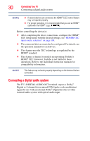
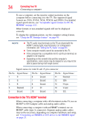
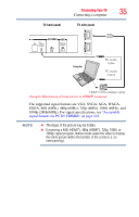
34 Connecting Your TV Connecting a computer To use a computer, set the monitor output resolution on the computer before connecting it to the TV. The supported signal formats are VGA, SVGA, XGA, WXGA and SXGA. For detailed signal specifications, see "Acceptable signal formats for PC IN, HDMI®" on page 122. Other formats or non-standard signals will not be displayed correctly. To display the optimum picture, use the computer setting feature, see "Using the PC Settings feature" on page 93. NOTE ❖ The PC audio input terminals on the TV are shared with the HDMI 1 analog audio input terminals. For configuration information, see "Setting the PC Audio" on page 94. ❖ Some computer models cannot be connected to this TV. ❖ If the computer has a compatible mini D-sub15-pin terminal, an adapter is not required. ❖ Depending on the content's title and the computer's specifications, some scenes may be skipped or you may not be able to pause during multi-angle scenes. Signal names for mini D-sub 15-pin connector: Pin No.: Signal Name: Pin No.: Signal Name: Pin No.: Signal Name: 1 R 6 Ground 11 Reserved 2 G 7 Ground 12 SDA 3 B 8 Ground 13 H-sync 4 Reserved 9 5V 14 V-sync 5 Ground 10 Ground 15 SCL Connection to the TV's HDMI® terminal When connecting a computer with a DVI terminal on the TV, use an HDMI®-to-DVI adapter cable and analog audio cables. When connecting a computer with an HDMI® terminal, use an HDMI® cable (type A connector). Separate analog audio cables may not be necessary, depending on computer hardware and setup, see "Connecting an HDMI® or DVI device to the HDMI® input" on page 27.
-
 1
1 -
2
-
3
-
4
-
5
-
6
-
7
-
8
-
9
-
10
-
11
-
12
-
13
-
14
-
15
-
16
-
17
-
18
-
19
-
20
-
21
-
22
-
23
-
24
-
25
-
26
-
27
-
28
-
 29
29 -
 30
30 -
 31
31 -
 32
32 -
 33
33 -
 34
34 -
 35
35 -
 36
36 -
 37
37 -
 38
38 -
 39
39 -
40
-
41
-
42
-
43
-
44
-
45
-
46
-
47
-
48
-
49
-
50
-
51
-
52
-
53
-
54
-
55
-
56
-
57
-
58
-
59
-
60
-
61
-
62
-
63
-
64
-
65
-
66
-
67
-
68
-
69
-
70
-
71
-
72
-
73
-
74
-
75
-
76
-
77
-
78
-
79
-
80
-
81
-
82
-
83
-
84
-
85
-
86
-
87
-
88
-
89
-
90
-
91
-
92
-
93
-
94
-
95
-
96
-
97
-
98
-
99
-
100
-
101
-
102
-
103
-
104
-
105
-
106
-
107
-
108
-
109
-
110
-
111
-
112
-
113
-
114
-
115
-
116
-
117
-
118
-
119
-
120
-
121
-
122
-
123
-
124
-
125
-
126
-
127
-
128
-
129
-
130
-
131
 |
 |