Toshiba BDX2000KU Owner's Manual - English - Page 8
Front Panel, Rear Panel
 |
View all Toshiba BDX2000KU manuals
Add to My Manuals
Save this manual to your list of manuals |
Page 8 highlights
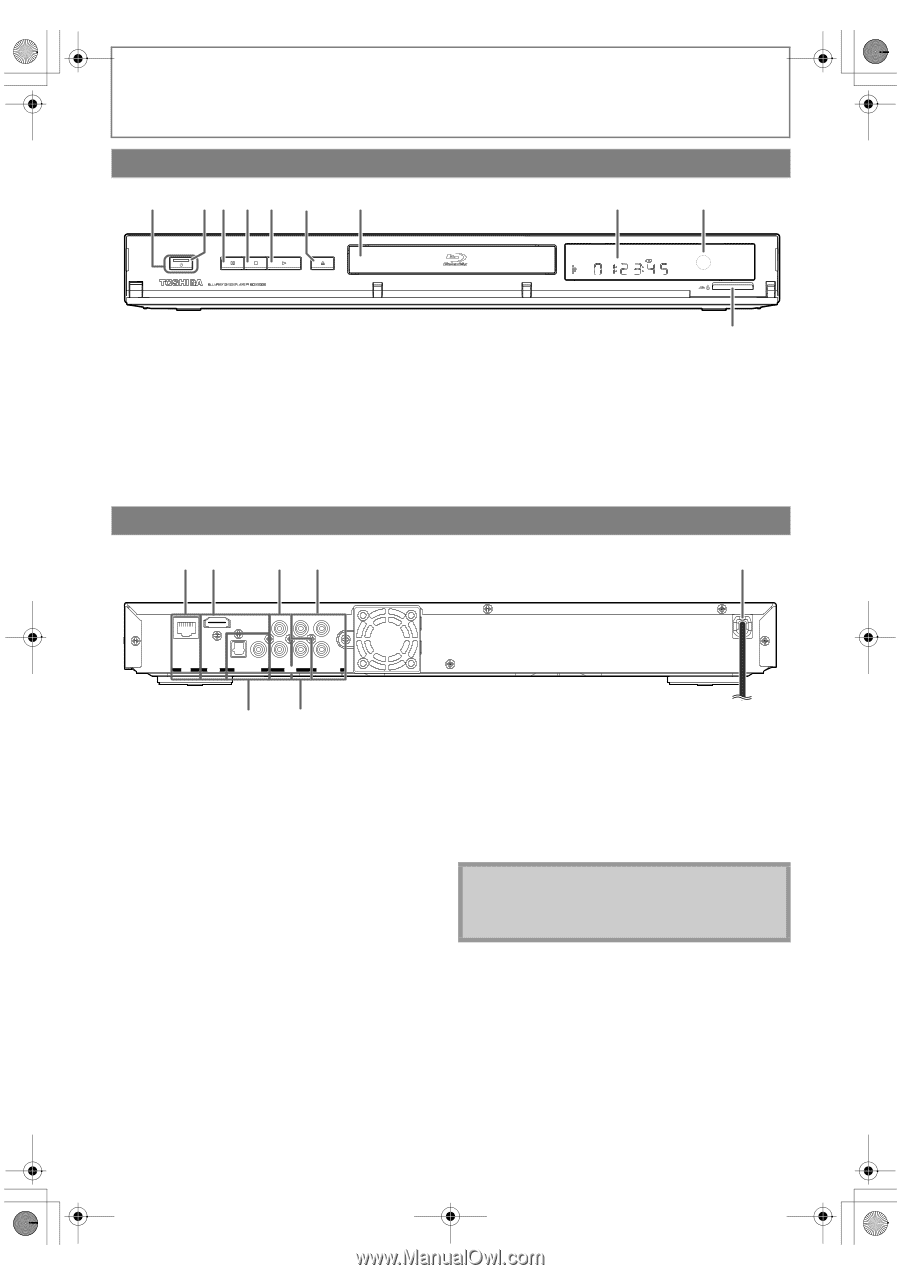
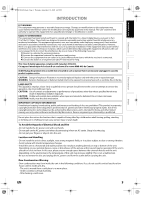
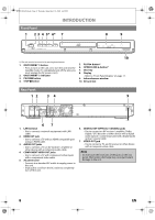
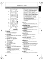
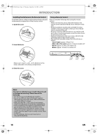
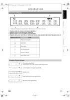
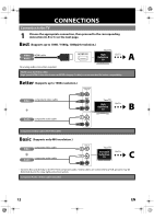
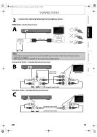
E5PJ1UD_EN.book Page 8 Thursday, September 10, 2009 6:45 PM INTRODUCTION Front Panel 1 2 3 4 5* 6* 7 8 9 ON/STANDBY PAUSE STOP PLAY OPEN/CLOSE (*) The unit can also be turned on by pressing these buttons. 1. ON/STANDBY Q button • Press to turn on the unit, or to turn the unit into the standby mode. (To completely turn off the unit, you must unplug the AC power cord.) 2. ON/STANDBY Q indicator 3. PAUSE F button 4. STOP C button 10 5. PLAY B button* 6. OPEN/CLOSE A button* 7. Disc tray 8. Display • Refer to "Front Panel Display" on page 11. 9. Infrared sensor window 10. SD card slot Rear Panel 12 3 4 5 L Y PR/CR OPTICAL COAXIAL R PB/CB LAN HDMI OUT DIGITAL OUT PCM / BITSTREAM AUDIO VIDEO OUT COMPONENT VIDEO OUT 67 1. LAN terminal • Use to connect a network equipment with LAN cable. 2. HDMI OUT jack • Use to connect a TV with an HDMI compatible port using an HDMI cable. 3. AUDIO OUT jacks • Use to connect a TV, an AV receiver / amplifier or other device with a composite audio cable. 4. COMPONENT VIDEO OUT jacks • Use to connect a TV with component video inputs with a component video cable. 5. AC power cord • Connect to a standard AC outlet to supply power to this unit. • Unplug this cord from the AC outlet to completely turn off the unit. 6. DIGITAL OUT (OPTICAL / COAXIAL) jacks • Use to connect an AV receiver / amplifier, Dolby Digital / DTS decoder or other device with a digital audio optical / coaxial input jack with a digital audio optical / coaxial cable. 7. VIDEO OUT jack • Use to connect a TV, an AV receiver or other device with a composite video cable. Note • Do not touch the inner pins of the jacks on the rear panel. Electrostatic discharge may cause permanent damage to the unit. 8 EN
-
 1
1 -
2
-
 3
3 -
 4
4 -
 5
5 -
 6
6 -
 7
7 -
 8
8 -
 9
9 -
 10
10 -
 11
11 -
 12
12 -
 13
13 -
14
-
15
-
16
-
17
-
18
-
19
-
20
-
21
-
22
-
23
-
24
-
25
-
26
-
27
-
28
-
29
-
30
-
31
-
32
-
33
-
34
-
35
-
36
-
37
-
38
-
39
-
40
-
41
-
42
-
43
-
44
-
45
-
46
-
47
-
48
-
49
-
50
-
51
-
52
-
53
-
54
-
55
-
56
-
57
-
58
-
59
-
60
-
61
-
62
-
63
-
64
 |
 |