Toshiba P47LSB User Manual - Page 30
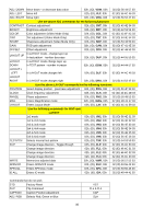
High signal level: Contrast common for Video/RGB Gain RGB only - computers
 |
View all Toshiba P47LSB manuals
Add to My Manuals
Save this manual to your list of manuals |
Page 30 highlights
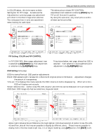
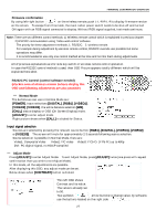
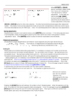
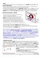
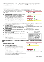
There are two stages for white balance or color balance adjustment to allow adjustment of low-signallevel and high-signal-level portions of the image. Use external test signal software or signal source for the picture, then enter to adjust mode. Low signal level: Brightness ( common for Video/RGB ) High signal level: Contrast ( common for Video/RGB ) Offset ( RGB only ) Gain ( RGB only ) These models, P42/47LSA+ and P42/47LSB are equipped a Ballast power control for 8 steps of lamp power. This lamp power control will affect for the entire brightness of the panel so that before the color balance adjustment, display a 100% white signal and match the brightness by Lamp Power control (refer to SERVICE mode). Before this setting, all the color balance controls are reset to the factory electronic adjustment position. The higher the lamp power the brighter the image but the lamp life is reduced. For low-signal level adjustment, 10-20% IRE signal is required and this should be provided by the signal source to be used (i.e. if video is the source, a video test pattern generator should be used and if computer is the main source, test pattern generating software should be used) for accurate adj. result. [BRIGHT] will control the overall brightness of the image and is mainly used as a low signal level adjustment. If PC images are main signal, then [OFFSET] will take care of adjustment before AD converter. Adjust RGB separately using [ADJ.R], [ADJ.G] and [ADJ.B] buttons. When Video signal is supplied, there is no OFFSET adjustment. For high-signal level adjustment, around 70-80-90% IRE signal is required. In this occasion, [CONT.] will control the overall level of the image and [GAIN] will take care for PC signal. The [GAIN] has an [ADJ.R], [ADJ.G] or [ADJ.B] selection. This GAIN adjustment is for RGB-HV signal only, not for video. Cutoff and Drive Unlike as CRT or DLP type, these LCD monitors have not final stage adjustment such as Cut-off and Drive. No function applied for these buttons. CLOCK frequency adjustment and PHASE adjustment Supply fine pitch signal (such as Windows shut-down screen) and adjust [CLOCK] and [PHASE] to eliminate moiré and jitter. These adjustments are only for PC, analog RGB input. Image position Adjustment, [POSI.] Use [POSI.] to electronically shift the image. [CAP.], image capture is not used. Video Enhancer When video input is selected, the following adjustments are available: [COLOR], [TINT] (NTSC only) and [SHARP]. Image Orientation [FLIP] The image orientation can be flipped up, down, left and right using the [FLIP] key. Status Indication [CALL] Pressing [CALL] in Normal Mode will display general information such as input selection and source frequency. In Adjust mode, it will turn off OSD and [WRITE] will record OSD mute. Factory reset [STD] key OK to reset? Yes: [STD] No: [ADJUST] This key will reset all adjusted data. The on-screen-display will confirm if this function should be performed or not. Pressing the [STD] key again will erase all the adjustment data are reset to factory values. Internal Test Pattern [TEST.P] Access Internal Test Patterns by pressing [TEST.P] while in Adjust Mode. Pressing [TEST.P] several times will cycle through the available patterns or, individual patterns can be selected by entering the relevant two digit number. For example, press [TEST.P], [7], [TEST.P] to access test signal #7. Also, left side, Up or Down key will advance or reverse one step each. Use [ADJUST] to escape. RS232C CONTROL 30
-
 1
1 -
2
-
3
-
4
-
5
-
6
-
7
-
8
-
9
-
10
-
11
-
12
-
13
-
14
-
15
-
16
-
17
-
18
-
19
-
20
-
21
-
22
-
23
-
24
-
 25
25 -
 26
26 -
 27
27 -
 28
28 -
 29
29 -
 30
30 -
 31
31 -
 32
32 -
 33
33 -
 34
34 -
 35
35 -
36
-
37
-
38
-
39
-
40
-
41
-
42
-
43
-
44
-
45
-
46
 |
 |