Toshiba P47LSB User Manual - Page 41
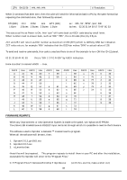
V 11.2A, 18V 6A, 24V Fan 0.5A, 5V 1.5A are coming out. 24V is for lamp ballast, 18V is
 |
View all Toshiba P47LSB manuals
Add to My Manuals
Save this manual to your list of manuals |
Page 41 highlights
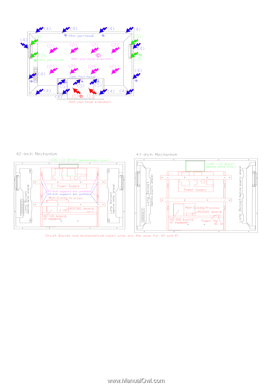
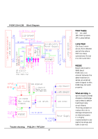
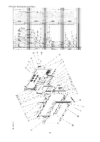
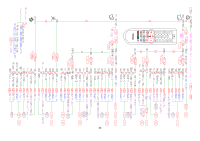
Below pictures are 42-inch and 47-inch parts locations. Both models are using the same internal mechanism which is indicated by red color, only two support bars are attached at different locations. Handles are also written, the picture is indicating that These handles are come in handy when servicing. Place the LCD monitor on a desk covered with some soft material such as blanket. We recommend preparing a plastic container or cup, (5 or 6 pcs) to sort out different screws, this will help to re-assemble the set. 1) Remove stand, if attached, by two screws, see (1) screws. 2) Remove 8 pcs of 8mm screws used for wall mount fastening screws. (2) 3) Remove 4 pcs of 6mm screws used to fasten handles. (3) 4) Remove all 12 pcs of rear panel fastening screws. (4) 5) Remove 3 small, 3mm flat head screws. (5) 6) Remove black colored rear panel. Rear cover is tightly fit, lift little by little and remove the panel carefully. Location of circuit boards When the rear cover removed, the circuit boards are accessible for most of the inspections. Although two ballast (lamp power supply) boards are behind the metal (42-inch) and plastic (47-inch) cover. LCD Driver board (LVDS board) is covered by metal shield, at the position of green color area. There is no potentiometer on these boards to make an adjustment, all the adjustments are embedded in the firmware of the system. Power Supply Power supply has several output voltages. 24V 11.2A, 18V 6A, 24V Fan 0.5A, 5V 1.5A are coming out. 24V is for lamp ballast, 18V is for main scaling process board and LVDS LCD driver board, 5V is not used. Thus 1st inspection for trouble shooting is 24V and 18V, also inspection of AC main fuse, T8A, 250V. Lamps are attached to the LCD panel with light diffuser plastic sheet and light reflector, they are assembled together and impossible to replace lamps only. When the lamps came to their life-end, the LCD panel material also almost came to the end of its life, thus replace LCD/Lamp assembly if needed. The input signals are received at Main process board and then scaling function applied by the same board. All the control is done by its firmware. An E-EPROM41contains all the operation control firmware and replacing it will result in a version change. A version up-grade can also be done by RS232C firmware rewrite operation. The P42LSA+ and P47LSA+ firmware is the same since both panels have the same resolution, 1920x1080. This is also the same to P42LSB and P47LSB. There is no compatibility between
-
 1
1 -
2
-
3
-
4
-
5
-
6
-
7
-
8
-
9
-
10
-
11
-
12
-
13
-
14
-
15
-
16
-
17
-
18
-
19
-
20
-
21
-
22
-
23
-
24
-
25
-
26
-
27
-
28
-
29
-
30
-
31
-
32
-
33
-
34
-
35
-
 36
36 -
 37
37 -
 38
38 -
 39
39 -
 40
40 -
 41
41 -
 42
42 -
 43
43 -
 44
44 -
 45
45 -
 46
46
 |
 |