Toshiba Qosmio X500 PQX33C-03L00N Users Manual Canada; English - Page 164
degree angle. Press the module carefully to ensure a firm, place to secure the module.
 |
View all Toshiba Qosmio X500 PQX33C-03L00N manuals
Add to My Manuals
Save this manual to your list of manuals |
Page 164 highlights
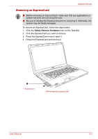
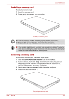
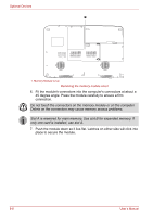
Optional Devices 1 1. Memory Module Cover Removing the memory module cover 6. Fit the module's connectors into the computer's connectors at about a 45 degree angle. Press the module carefully to ensure a firm connection. Do not touch the connectors on the memory module or on the computer. Debris on the connectors may cause memory access problems. Slot A is reserved for main memory. Use slot B for expanded memory. If only one card is installed, use slot A. 7. Push the module down so it lies flat. Latches on either side will click into place to secure the module. 8-8 User's Manual
-
 1
1 -
2
-
3
-
4
-
5
-
6
-
7
-
8
-
9
-
10
-
11
-
12
-
13
-
14
-
15
-
16
-
17
-
18
-
19
-
20
-
21
-
22
-
23
-
24
-
25
-
26
-
27
-
28
-
29
-
30
-
31
-
32
-
33
-
34
-
35
-
36
-
37
-
38
-
39
-
40
-
41
-
42
-
43
-
44
-
45
-
46
-
47
-
48
-
49
-
50
-
51
-
52
-
53
-
54
-
55
-
56
-
57
-
58
-
59
-
60
-
61
-
62
-
63
-
64
-
65
-
66
-
67
-
68
-
69
-
70
-
71
-
72
-
73
-
74
-
75
-
76
-
77
-
78
-
79
-
80
-
81
-
82
-
83
-
84
-
85
-
86
-
87
-
88
-
89
-
90
-
91
-
92
-
93
-
94
-
95
-
96
-
97
-
98
-
99
-
100
-
101
-
102
-
103
-
104
-
105
-
106
-
107
-
108
-
109
-
110
-
111
-
112
-
113
-
114
-
115
-
116
-
117
-
118
-
119
-
120
-
121
-
122
-
123
-
124
-
125
-
126
-
127
-
128
-
129
-
130
-
131
-
132
-
133
-
134
-
135
-
136
-
137
-
138
-
139
-
140
-
141
-
142
-
143
-
144
-
145
-
146
-
147
-
148
-
149
-
150
-
151
-
152
-
153
-
154
-
155
-
156
-
157
-
158
-
 159
159 -
 160
160 -
 161
161 -
 162
162 -
 163
163 -
 164
164 -
 165
165 -
 166
166 -
 167
167 -
 168
168 -
 169
169 -
170
-
171
-
172
-
173
-
174
-
175
-
176
-
177
-
178
-
179
-
180
-
181
-
182
-
183
-
184
-
185
-
186
-
187
-
188
-
189
-
190
-
191
-
192
-
193
-
194
-
195
-
196
-
197
-
198
-
199
-
200
-
201
-
202
-
203
-
204
-
205
-
206
-
207
-
208
-
209
-
210
-
211
-
212
-
213
-
214
-
215
-
216
-
217
-
218
-
219
-
220
-
221
-
222
-
223
 |
 |
8-8
User’s Manual
Optional Devices
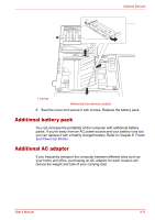
Removing the memory module cover
6.
Fit the module's connectors into the computer's connectors at about a
45 degree angle. Press the module carefully to ensure a firm
connection.
7.
Push the module down so it lies flat. Latches on either side will click into
place to secure the module.
1
1. Memory Module Cover
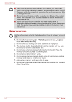
Do not touch the connectors on the memory module or on the computer.
Debris on the connectors may cause memory access problems.
Slot A is reserved for main memory. Use slot B for expanded memory. If
only one card is installed, use slot A.