Toshiba Satellite T130 PST3AA-02F006 Users Manual AU/NZ - Page 110
module carefully to ensure a firm connection., place to secure the module.
 |
View all Toshiba Satellite T130 PST3AA-02F006 manuals
Add to My Manuals
Save this manual to your list of manuals |
Page 110 highlights
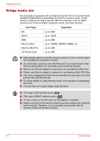
Optional Devices 1 1. Memory Module Cover Removing the memory module cover 6. Lift one side of the insulator sheet and fit the module's connectors into the computer's connectors at about a 30 degree angle. Press the module carefully to ensure a firm connection. Do not touch the connectors on the memory module or on the computer. Debris on the connectors may cause memory access problems. Slot A is reserved for main memory. Use slot B for expanded memory. If only one card is installed use slot A. 7. Push the module down so it lies flat. Latches on either side will click into place to secure the module. 2 1 1. Slot A 2. Slot B Installing the memory module User's Manual 8-7
-
 1
1 -
2
-
3
-
4
-
5
-
6
-
7
-
8
-
9
-
10
-
11
-
12
-
13
-
14
-
15
-
16
-
17
-
18
-
19
-
20
-
21
-
22
-
23
-
24
-
25
-
26
-
27
-
28
-
29
-
30
-
31
-
32
-
33
-
34
-
35
-
36
-
37
-
38
-
39
-
40
-
41
-
42
-
43
-
44
-
45
-
46
-
47
-
48
-
49
-
50
-
51
-
52
-
53
-
54
-
55
-
56
-
57
-
58
-
59
-
60
-
61
-
62
-
63
-
64
-
65
-
66
-
67
-
68
-
69
-
70
-
71
-
72
-
73
-
74
-
75
-
76
-
77
-
78
-
79
-
80
-
81
-
82
-
83
-
84
-
85
-
86
-
87
-
88
-
89
-
90
-
91
-
92
-
93
-
94
-
95
-
96
-
97
-
98
-
99
-
100
-
101
-
102
-
103
-
104
-
 105
105 -
 106
106 -
 107
107 -
 108
108 -
 109
109 -
 110
110 -
 111
111 -
 112
112 -
 113
113 -
 114
114 -
 115
115 -
116
-
117
-
118
-
119
-
120
-
121
-
122
-
123
-
124
-
125
-
126
-
127
-
128
-
129
-
130
-
131
-
132
-
133
-
134
-
135
-
136
-
137
-
138
-
139
-
140
-
141
-
142
-
143
-
144
-
145
-
146
-
147
-
148
-
149
-
150
-
151
-
152
-
153
-
154
-
155
-
156
-
157
-
158
-
159
 |
 |
User’s Manual
8-7
Optional Devices
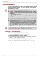
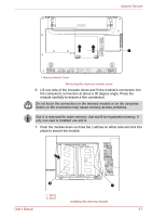
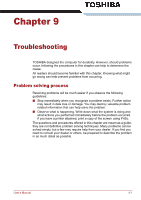
Removing the memory module cover
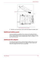
6.
Lift one side of the insulator sheet and fit the module's connectors into
the computer's connectors at about a 30 degree angle. Press the
module carefully to ensure a firm connection.
7.
Push the module down so it lies flat. Latches on either side will click into
place to secure the module.
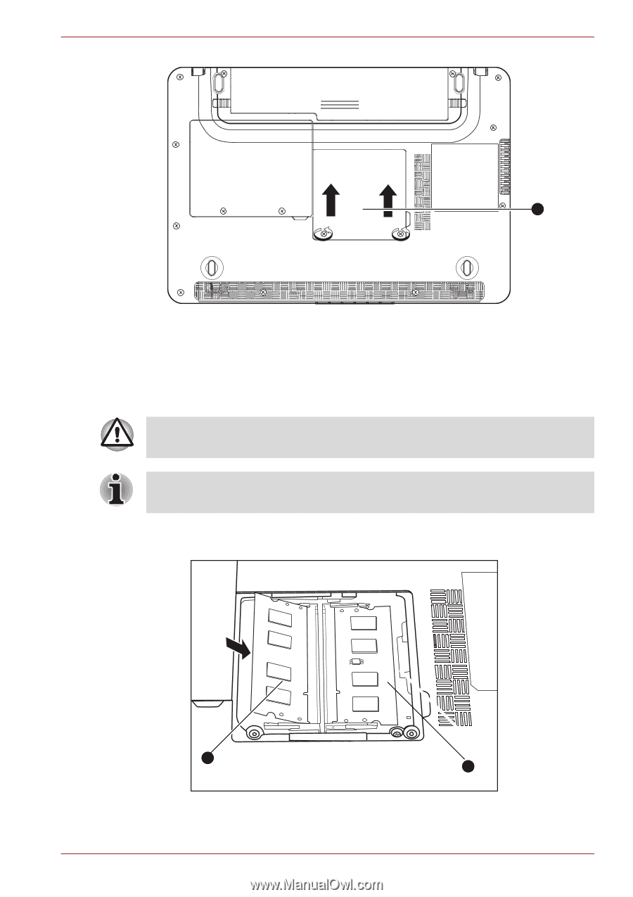
Installing the memory module
1. Memory Module Cover
1
Do not touch the connectors on the memory module or on the computer.
Debris on the connectors may cause memory access problems.
Slot A is reserved for main memory. Use slot B for expanded memory. If
only one card is installed use slot A.
1
2
1. Slot A
2. Slot B