Toshiba Tecra W50-A5160SM User Manual - Page 92
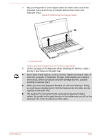
locking tabs on the connector and insert the module into the connector
 |
View all Toshiba Tecra W50-A5160SM manuals
Add to My Manuals
Save this manual to your list of manuals |
Page 92 highlights
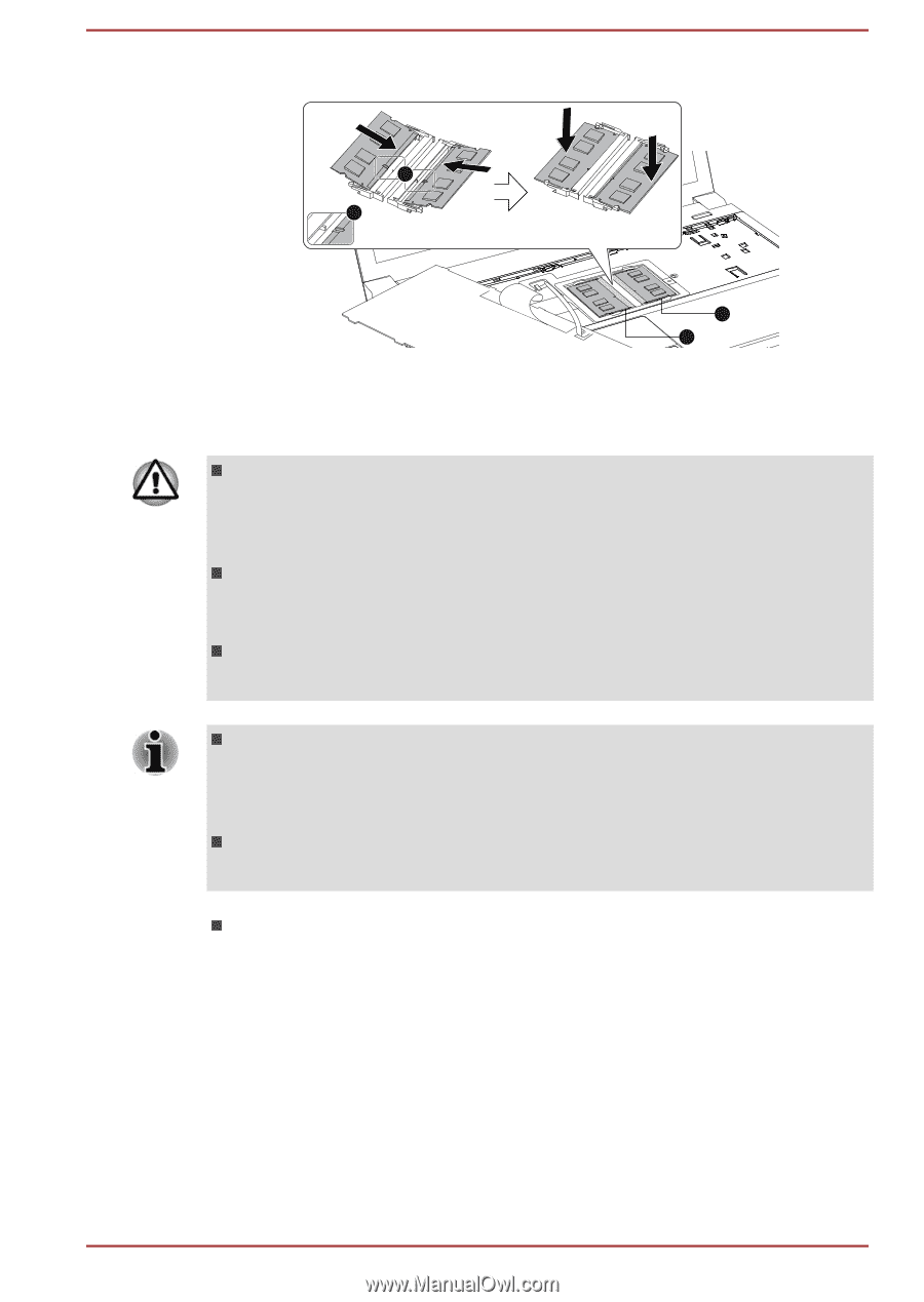
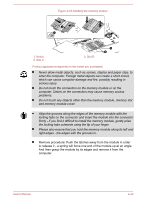
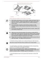
Figure 4-19 Installing the memory module 1 1 1. Notch 2. Slot C 3. Slot D 3 2 Product appearance depends on the model you purchased. Never allow metal objects, such as screws, staples and paper clips, to enter the computer. Foreign metal objects can create a short circuit, which can cause computer damage and fire, possibly resulting in serious injury. Do not touch the connectors on the memory module or on the computer. Debris on the connectors may cause memory access problems. Do not touch any objects other than the memory module, memory slot and memory module cover. Align the grooves along the edges of the memory module with the locking tabs on the connector and insert the module into the connector firmly - if you find it difficult to install the memory module, gently prise the locking tabs outwards using the tip of your finger. Please also ensure that you hold the memory module along its left and right edges - the edges with the grooves in. Remove procedure: Push the latches away from the module in order to release it - a spring will force one end of the module up at an angle. And then grasp the module by its edges and remove it from the computer. User's Manual 4-42
-
 1
1 -
2
-
3
-
4
-
5
-
6
-
7
-
8
-
9
-
10
-
11
-
12
-
13
-
14
-
15
-
16
-
17
-
18
-
19
-
20
-
21
-
22
-
23
-
24
-
25
-
26
-
27
-
28
-
29
-
30
-
31
-
32
-
33
-
34
-
35
-
36
-
37
-
38
-
39
-
40
-
41
-
42
-
43
-
44
-
45
-
46
-
47
-
48
-
49
-
50
-
51
-
52
-
53
-
54
-
55
-
56
-
57
-
58
-
59
-
60
-
61
-
62
-
63
-
64
-
65
-
66
-
67
-
68
-
69
-
70
-
71
-
72
-
73
-
74
-
75
-
76
-
77
-
78
-
79
-
80
-
81
-
82
-
83
-
84
-
85
-
86
-
 87
87 -
 88
88 -
 89
89 -
 90
90 -
 91
91 -
 92
92 -
 93
93 -
 94
94 -
 95
95 -
 96
96 -
 97
97 -
98
-
99
-
100
-
101
-
102
-
103
-
104
-
105
-
106
-
107
-
108
-
109
-
110
-
111
-
112
-
113
-
114
-
115
-
116
-
117
-
118
-
119
-
120
-
121
-
122
-
123
-
124
-
125
-
126
-
127
-
128
-
129
-
130
-
131
-
132
-
133
-
134
-
135
-
136
-
137
-
138
-
139
-
140
-
141
-
142
-
143
-
144
-
145
-
146
-
147
-
148
-
149
-
150
-
151
-
152
-
153
-
154
-
155
-
156
-
157
-
158
-
159
-
160
-
161
-
162
-
163
-
164
-
165
-
166
-
167
 |
 |