Tripp Lite BP240V500C Owner s Manual for Extended-Run 3-Phase Battery Cabinet - Page 16
Battery and Breaker Diagrams
 |
View all Tripp Lite BP240V500C manuals
Add to My Manuals
Save this manual to your list of manuals |
Page 16 highlights
6. Diagrams 6.2 Battery and Breaker Diagrams 6.2.1 192 VDC (Single-Phase) 218 VDC 192 VDC 218 VDC (Charger adjusted and tested to 216-221 VDC at float) Notes: • All internal wiring is UL-listed, MTW, 105C Hi-Flex cable. • Terminal block is UL-recognized and rated for 600 VDC. • Breaker is UL-listed and rated for 50 A, 600 VDC, 42 KAIC. • Cabinets with breakers are shipped with the breaker in the off/open position and one of the jumper cables disconnected. • Battery arrangements shown are typical but may vary depending on cabinet and battery type. 16
-
 1
1 -
2
-
3
-
4
-
5
-
6
-
7
-
8
-
9
-
10
-
 11
11 -
 12
12 -
 13
13 -
 14
14 -
 15
15 -
 16
16 -
 17
17 -
 18
18 -
 19
19 -
 20
20 -
 21
21 -
22
-
23
-
24
-
25
-
26
-
27
-
28
-
29
-
30
-
31
-
32
-
33
-
34
-
35
-
36
-
37
-
38
-
39
-
40
-
41
-
42
-
43
-
44
 |
 |

16
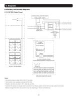
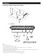
6. Diagrams
6.2 Battery and Breaker Diagrams
6.2.1 192 VDC (Single-Phase)
Notes:
• All internal wiring is UL-listed, MTW, 105C Hi-Flex cable.
• Terminal block is UL-recognized and rated for 600 VDC.
• Breaker is UL-listed and rated for 50 A, 600 VDC, 42 KAIC.
• Cabinets with breakers are shipped with the breaker in the off/open position and one of the jumper cables disconnected.
• Battery arrangements shown are typical but may vary depending on cabinet and battery type.
(Charger adjusted and tested to 216-221 VDC at float)
218 VDC
218 VDC
192 VDC