Tripp Lite SRCOOL18K Owners Manual - Page 4
Features
 |
View all Tripp Lite SRCOOL18K manuals
Add to My Manuals
Save this manual to your list of manuals |
Page 4 highlights
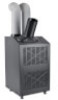
Features SRCOOL18K/SRCOOL24K A Cool Air Output B Louvered Vent Insert (Pre-Installed) C Warm Air Exhaust D SNMP Accessory Slot* * SNMP card pre-installed with SRCOOL24K model E Control Panel F Casters G Condenser Filters (Included - see Maintenance section for filter replacement) H Front Panel I Cooling Duct Adapter (Optional, Varies by Model) J Evaporator Filters (Included - see Maintenance section for filter replacement) K Rear Panel L Evaporator Drainage Outlets Control Panel M Numeric Display N Operating Mode LEDs O Temperature Control Buttons P Fan Speed Mode LEDs Q "FAN SPEED" Button R "QUIET" LED S "QUIET" Button T "TIMER" Button U "FUNCTION" Button V "POWER" Button SNMP Connections (SRCOOL24K Only) O W PS/2 Port (for use with ENVIROSENSE accessory - included with SRCOOL24K) X Mini-DIN Serial Port Y RJ45 Ethernet Network Port R Z SNMP Reset Button S Note: Use a pin, paper clip, or point tool to access the recessed reset button. Do not use excessive force when engaging the reset button. B A SRCOOL18K/SRCOOL24K Front View C D E H F G L M J SRCOOK18K SRCOOK24K I K SRCOOL18K/SRCOOL24K Rear View N W X Y P Q T SNMP Connections Z Control Panel U V 4
-
 1
1 -
 2
2 -
 3
3 -
 4
4 -
 5
5 -
 6
6 -
 7
7 -
 8
8 -
 9
9 -
 10
10 -
11
-
12
-
13
-
14
-
15
-
16
-
17
-
18
-
19
-
20
-
21
-
22
-
23
-
24
-
25
-
26
-
27
-
28
-
29
-
30
-
31
-
32
-
33
-
34
-
35
-
36
-
37
-
38
-
39
-
40
 |
 |
