Tripp Lite SRCOOL18K Owners Manual - Page 5
Installation
 |
View all Tripp Lite SRCOOL18K manuals
Add to My Manuals
Save this manual to your list of manuals |
Page 5 highlights
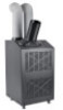
Installation Warning: After removing the unit from the shipping container, check for damage or missing parts (refer to the parts list below). If you notice a problem, visit www.tripplite.com/support for service. Do not attempt to operate a damaged unit. Accessory Parts List: SRCOOL18K 2 x Gray Exhaust Duct (Longer Tube) SRCOOL24K 1 x Black Cooling Duct (Shorter Tube) 2 x Exhaust Duct Adapter 2 x Adjustable Exhaust Panel (2 Sections) 4 x Self-Tapping Screw Cooling Duct Louvered Vent Insert Adapter (Optional) (Pre-installed) Drainage Plug (2 Pre-installed) 2 x Gray Exhaust Duct (Longer Tube) 2 x Black 2 x Exhaust Duct 2 x Adjustable 4 x Self-Tapping Cooling Duct Louvered Vent Drainage ENVIROSENSE Cooling Duct Adapter Exhaust Panel Screw Adapter - 2 pcs. Insert Plug Environmental (Shorter Tube) (2 Sections) (Optional) (Pre-installed) (2 Pre-installed) Sensor SNMP Configuration Cable 1 Unit Placement Place the unit on a flat, level surface near a grounded AC outlet rated in accordance with the unit nameplate (90-110% of specified voltage). Leave adequate space around the unit for ventilation, with the front and rear not less than 20 inches (51 cm) from walls or other obstacles. Place the unit in a location with convenient access to a drop ceiling or window to provide the straightest, shortest path available for the flexible exhaust duct. If you plan to use the flexible cooling duct to focus cool air on a specific rack enclosure or device, place the unit near the targeted rack enclosure or device to provide the straightest, shortest path available for the cooling duct. Warning: Do not use an extension cord to connect the unit to an AC outlet. Use only the power cord that came with the unit. Note: If the unit will operate in a confined space (such as closet), you must supply makeup air in order to maintain airflow efficiency. A 100 in.2 (645 cm2) or larger vent installed near the bottom of the door should supply adequate makeup air for a typical closet. Consult applicable building codes for more information. Exhaust hose not shown-see Section 3 . 1 100 in.2 (645 cm2) Vent (For Confined Spaces) > 20 in. (51 cm) > 20 in. (51 cm) WALL 2 Cooling Duct Connection (Optional) The pre-installed louvered vent insert is appropriate for room cooling applications. If you plan to cool a room, skip step 2 and proceed to step 3 . If you plan to use the flexible cooling duct to focus cool air on a specific device or rack enclosure, follow the instructions below. 2-1 Remove the louvered vent insert A by removing the screws B using a Phillips screwdriver and lifting the vent from the unit. B Note: The SRCOOL24K's cooling duct connection allows cool air to be split between two racks. A WALL 2-1 5
-
 1
1 -
 2
2 -
 3
3 -
 4
4 -
 5
5 -
 6
6 -
 7
7 -
 8
8 -
 9
9 -
 10
10 -
 11
11 -
12
-
13
-
14
-
15
-
16
-
17
-
18
-
19
-
20
-
21
-
22
-
23
-
24
-
25
-
26
-
27
-
28
-
29
-
30
-
31
-
32
-
33
-
34
-
35
-
36
-
37
-
38
-
39
-
40
 |
 |
