Tripp Lite SU1500RTXL2UA Owner's Manual for SmartOnline Rack/Tower UPS 932471 - Page 6
Installation
 |
View all Tripp Lite SU1500RTXL2UA manuals
Add to My Manuals
Save this manual to your list of manuals |
Page 6 highlights
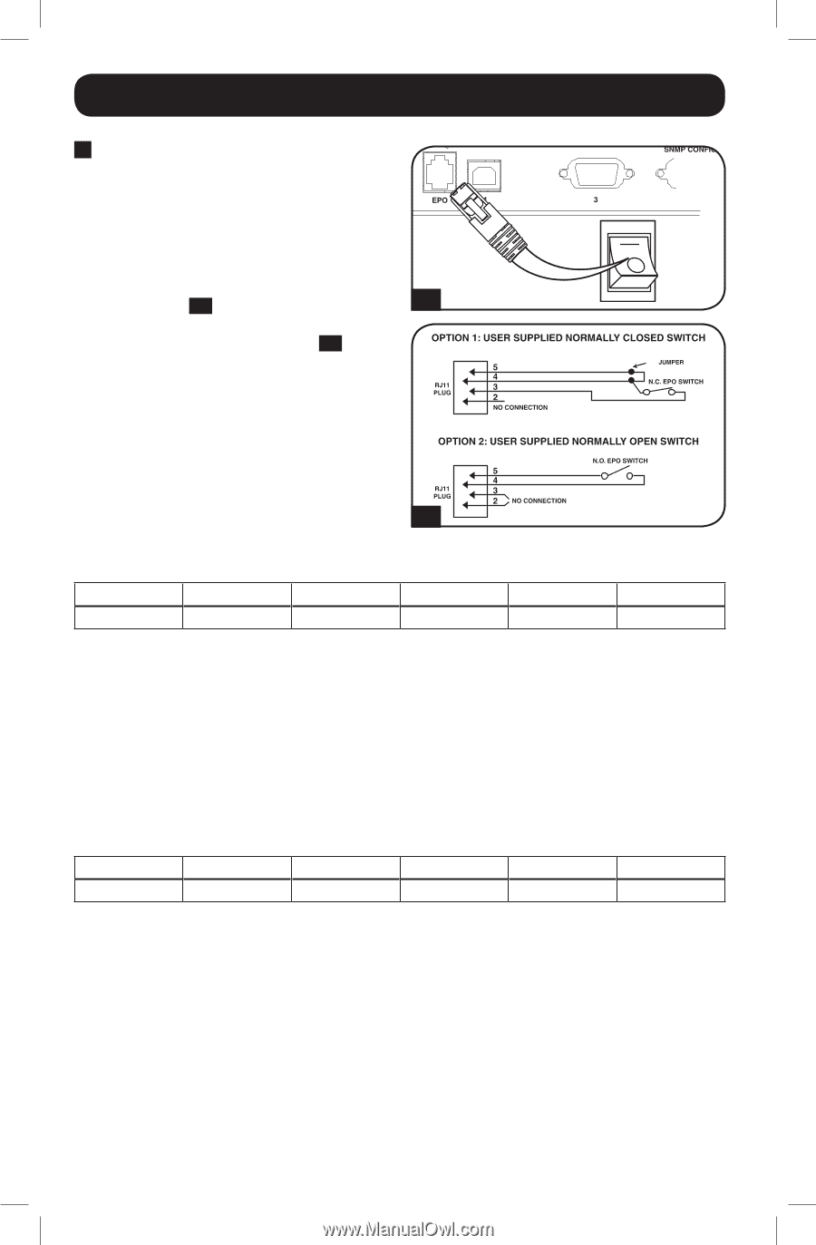
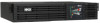
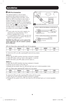
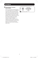
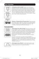
Installation 3 EPO Port Connection This optional feature is only for those applications that require connection to a facility's Emergency Power Off (EPO) circuit. When the UPS is connected to this circuit, it enables emergency shutdown of the UPS's inverter and inhibits transfer to internal bypass. Using the cable provided, connect the EPO port of your UPS (see 3a ) to a user-supplied 3a Your model may differ. normally closed or normally open switch according to the circuit diagram (see 3b ). 4-5 Note: 1. If using a cable other than what is supplied, the cable should not exceed 350 feet or have a resistance of greater than 10 ohms. 2. If a non-latching EPO switch is used, the EPO must be held for a minimum of 1 second. This does not apply to a latching EPO switch. CAUTION: The EPO port is not a phone line surge suppressor; do not connect a phone 3b line to this port. UPS Unit State when asserting EPO with AC line present: LEDs Output Fans Serial SNMP USB OFF OFF ON ON ON ON To restart the UPS unit after asserting EPO with AC line present: Option 1: 1. Verify that the EPO assertion has been removed or cleared. 2. Press OFF button until you hear a click (approx. 1 second). 3. Press ON button and UPS output will turn back on. Option 2: 1. Verify that the EPO assertion has been removed or cleared. 2. Remove AC line power to the UPS unit. 3. Reapply AC line power. Now the UPS will start back up in normal operation mode. UPS Unit State when asserting EPO without AC line power: LEDs Output Fans Serial SNMP USB OFF OFF OFF OFF OFF OFF To restart the UPS unit after asserting EPO without AC line power: 1. Verify that the EPO assertion has been removed or cleared. 2. Reapply AC line power to the UPS unit. Now the UPS will start back up in normal operation mode. 6 201102199 93-2471.indb 6 3/30/2011 9:14:01 AM
-
 1
1 -
 2
2 -
 3
3 -
 4
4 -
 5
5 -
 6
6 -
 7
7 -
 8
8 -
 9
9 -
 10
10 -
 11
11 -
 12
12 -
13
-
14
-
15
-
16
-
17
-
18
-
19
-
20
-
21
-
22
-
23
-
24
-
25
-
26
-
27
-
28
-
29
-
30
-
31
-
32
-
33
-
34
-
35
-
36
-
37
-
38
-
39
-
40
-
41
-
42
-
43
-
44
-
45
-
46
-
47
-
48
 |
 |