Tripp Lite SU3000RTXLCD2U Owner's Manual for SU3000RTXLCD2U UPS System 9332C3 - Page 6
Features
 |
View all Tripp Lite SU3000RTXLCD2U manuals
Add to My Manuals
Save this manual to your list of manuals |
Page 6 highlights
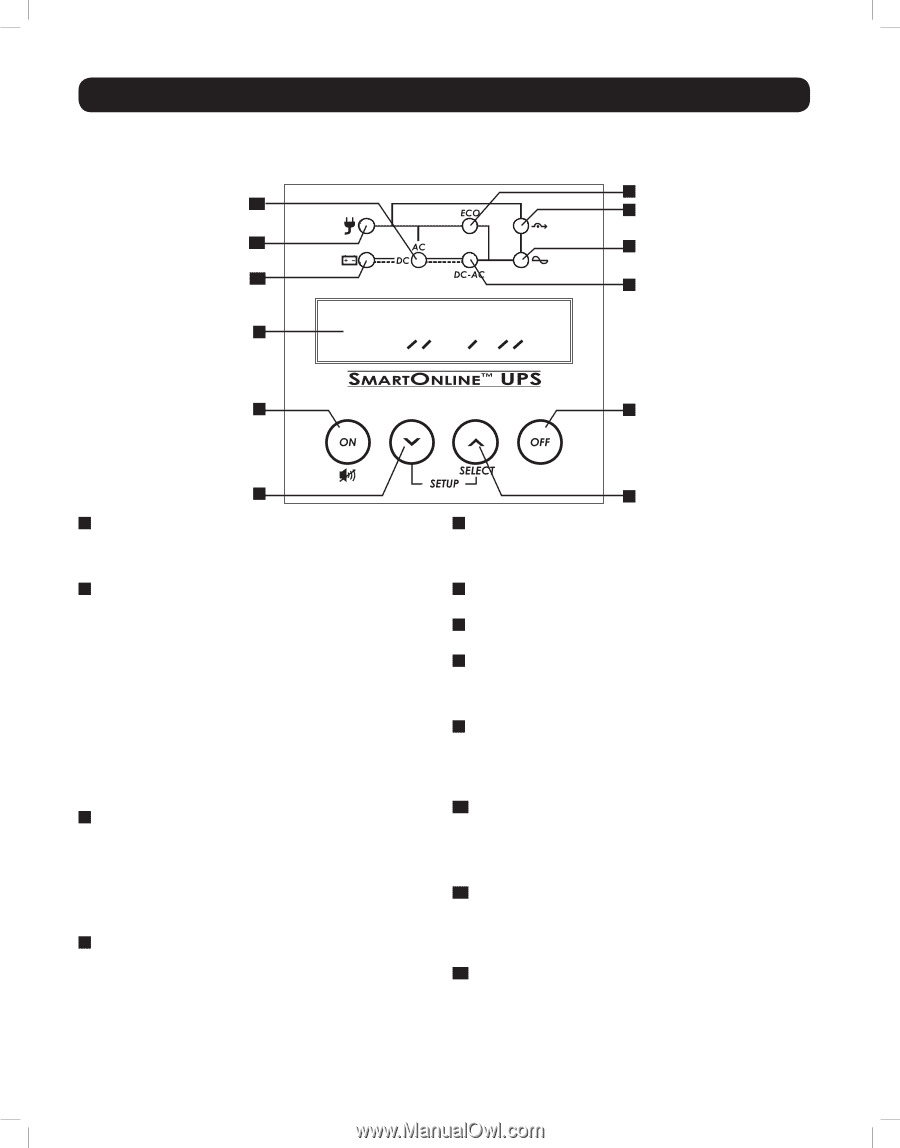
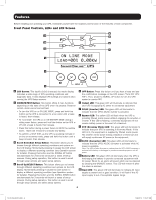
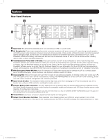
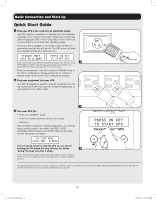
Features Before installing and operating your UPS, familiarize yourself with the locations and function of the features of each component. Front Panel Controls, LEDs and LCD Screen 9 10 8 12 6 11 7 1 2 5 3 4 1 LCD Screen: This backlit (16x2 character) dot matrix display indicates a wide range of UPS operating conditions and diagnostic data. It also displays UPS settings and options when viewing the UPS Setup screens. 2 ON/MUTE/TEST Button: This button offers 3 main functions depending on the state of the UPS when it's pressed: Power-on control, alarm-cancel and self-test. • To turn the UPS on in ON LINE MODE, press and hold this button as the UPS is connected to a live outlet until a beep is heard, then release. • To "cold start" the UPS on in ON BATTERY MODE during a utility power failure, press and hold this button as the UPS is off until a beep is heard, then release. • Press this button during a power failure to MUTE the audible alarm. Alarm will re-sound to indicate low-battery. • To perform a SELF TEST, as the UPS is operating normally in on-line or economy mode, press and hold this button until a beep is heard, then release. 3 Scroll Down/Exit Setup Button: This button allows you to browse through different operating conditions and options on the LCD display. Momentarily pressing it causes the LCD screen to display a different operating condition (see Operation section for details). Pressing this button and the SCROLL UP button simultaneously for 3 seconds will launch a series of setup screens. During setup operation, this button is used to scroll through setup options and select setup options. 4 Scroll Up/SELECT Button: This button allows you to browse through different operating conditions and options on the LCD display. Momentarily pressing it causes the LCD screen to display a different operating condition (see Operation section for details). Pressing this button and the SCROLL DOWN button simultaneously for 3 seconds will launch a series of setup screens. During setup operation, this button is used to scroll through setup options and select setup options. 5 OFF Button: Press this button until you hear a beep and see the confirmation message on the LCD screen ("Turn OFF UPS: Y/N"). Then, press the SCROLL UP button to turn the UPS system's inverter OFF. 6 Output LED: This green LED will illuminate to indicate that your UPS is supplying AC power to connected equipment. 7 DC/AC (Inverter) LED: This green LED will illuminate to indicate that the UPS's DC/AC inverter is activated. 8 Bypass LED: This yellow LED will flash when the UPS is providing filtered mains power without engaging its converter or inverter. If this LED is flashing, connected equipment will not receive battery power in the event of a blackout. 9 ECO (Economy Mode) LED: This green LED will illuminate to indicate that your UPS is operating in Economy Mode. If this LED is lit, the equipment is supplied by filtered mains power. The inverter will be active during a blackout or brownout and will supply continuous AC power to the equipment. 10 AC/DC (Converter) LED: This green LED will illuminate to indicate that the UPS's AC/DC converter is activated while AC power is available. Note: This LED will also illuminate to indicate that the UPS's DC/DC converter is activated while battery is discharged to provide connected equipment with AC power. 11 Battery LED: This green LED will illuminate when the UPS is discharging the battery to provide connected equipment with AC power. When lit, an alarm will sound which can be silenced by pressing the ON/MUTE button. This LED will remain lit after the alarm is silenced. 12 Input LED: This green LED will illuminate to indicate AC input supply is present and in good condition. It will flash if the AC input supply is out of acceptable bypass range. 6 13-07-015-9332C3.indb 6 7/26/2013 11:16:12 AM
-
 1
1 -
 2
2 -
 3
3 -
 4
4 -
 5
5 -
 6
6 -
 7
7 -
 8
8 -
 9
9 -
 10
10 -
 11
11 -
 12
12 -
13
-
14
-
15
-
16
-
17
-
18
-
19
-
20
-
21
-
22
-
23
-
24
-
25
-
26
-
27
-
28
-
29
-
30
-
31
-
32
-
33
-
34
-
35
-
36
-
37
-
38
-
39
-
40
-
41
-
42
-
43
-
44
-
45
-
46
-
47
-
48
-
49
-
50
-
51
-
52
-
53
-
54
-
55
-
56
-
57
-
58
-
59
-
60
-
61
-
62
-
63
-
64
-
65
-
66
-
67
-
68
-
69
-
70
-
71
-
72
-
73
-
74
-
75
-
76
-
77
-
78
-
79
-
80
 |
 |