Tripp Lite SU6000RT4UHV Owner's Manual for SmartOnline Single-Phase 5kVA-6kVA - Page 13
Accessory Slot, External Battery Connection
 |
View all Tripp Lite SU6000RT4UHV manuals
Add to My Manuals
Save this manual to your list of manuals |
Page 13 highlights
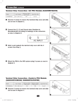
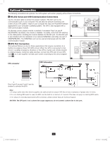
Optional Connection (continued) UPS Unit State when asserting EPO with AC line present: LEDs Output Fans Serial OFF OFF OFF OFF To restart the UPS unit after asserting EPO with AC line present: SNMP OFF USB LCD Screen OFF "Emergency Stop" 1. Verify that the EPO assertion has been removed or cleared. 2. Remove AC line power to the UPS unit. 3. Reapply AC line power. Now the UPS will start back up in Bypass mode and the LCD will display "BYPASS MODE". UPS Unit State when asserting EPO without AC line power: LEDs Output Fans Serial OFF OFF OFF OFF SNMP OFF USB LCD Screen OFF "Emergency Stop" To restart the UPS unit after asserting EPO without AC line power: 1. Verify that the EPO assertion has been removed or cleared. 2. Reapply AC line power to the UPS unit. Now the UPS will start back up in Bypass mode and the LCD will display "BYPASS MODE". 3 External Battery Connection Your UPS comes with a robust internal battery system; external batteries are needed NORMAL only to extend runtime. Adding external batteries will increase recharge time as well as runtime. The illustration shows the location of your UPS's External Battery Connector, where you will insert the battery pack cable. Complete installation instructions for your battery pack appear in the battery pack Owner's Manual. Make sure that cables are fully inserted into their connectors. Small sparks may result during battery connection; this is normal. Do not connect or disconnect battery packs when the UPS is running on battery power. 3 4 Accessory Slot Remove the slot's cover to install an optional internal SNMP/Web accessory card (Model: SNMPWEBCARD) to enable remote UPS monitoring and control via SNMP, Web or telnet. (Tripp Lite's RELAYIOCARD is also available.) Visit www.tripplite.com/ 4 support for more information, including a list of available SNMP, network management and connectivity products. 13 201207113 933070.indb 13 9/17/2012 1:20:04 PM
-
 1
1 -
2
-
3
-
4
-
5
-
6
-
7
-
 8
8 -
 9
9 -
 10
10 -
 11
11 -
 12
12 -
 13
13 -
 14
14 -
 15
15 -
 16
16 -
 17
17 -
 18
18 -
19
-
20
-
21
-
22
-
23
-
24
-
25
-
26
-
27
-
28
-
29
-
30
-
31
-
32
-
33
-
34
-
35
-
36
-
37
-
38
-
39
-
40
-
41
-
42
-
43
-
44
-
45
-
46
-
47
-
48
-
49
-
50
-
51
-
52
-
53
-
54
-
55
-
56
-
57
-
58
-
59
-
60
-
61
-
62
-
63
-
64
-
65
-
66
-
67
-
68
-
69
-
70
-
71
-
72
-
73
-
74
-
75
-
76
-
77
-
78
-
79
-
80
-
81
-
82
-
83
-
84
-
85
-
86
-
87
-
88
-
89
-
90
-
91
-
92
-
93
-
94
-
95
-
96
-
97
-
98
-
99
-
100
-
101
-
102
-
103
-
104
-
105
-
106
-
107
-
108
-
109
-
110
-
111
-
112
-
113
-
114
-
115
-
116
 |
 |