Troy-Bilt Bronco CRT Operation Manual - Page 17
Service - rear tine tiller
 |
View all Troy-Bilt Bronco CRT manuals
Add to My Manuals
Save this manual to your list of manuals |
Page 17 highlights
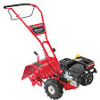
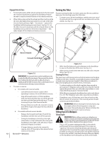
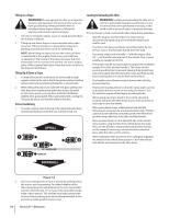
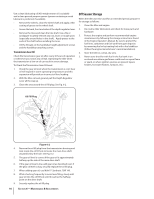
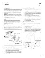
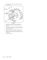
Service 7 Belt Replacement If the drive belt or reverse drive belt needs to be replaced, see your local authorized dealer or refer to the Replacement Parts Section for ordering information. Use only a factory-authorized belt as an "over- the-counter" belt may not perform satisfactorily. The procedure requires average mechanical ability and commonly available tools. NOTE: When reinstalling the belt cover, be sure to engage the bail and hold it so that the drive belt is tight before attempting to reinstall the belt cover. This will enable the belt to fall under the belt keeping mechanism built into the belt cover. Failure to do so could damage the belt and/or belt cover. Tines The bolo tines will wear with use and should be inspected at the beginning of each tilling season and after every 30 operating hours. The tines can be replaced either individually or as a complete set. See the Replacement Parts Section for tine identification and part numbers. Tine Inspection With use, the tines will become shorter, narrower and pointed. Badly worn tines will result in a loss of tilling depth, and reduced effectiveness when chopping up and turning under organic matter. Refer to Fig. 7-1 for the following tine procedures. Rear/Operator Removing/Installing a Tine Assembly: 1. A tine assembly consists of eight tines mounted on a tine holder. 2. If removing both tine assemblies, mark them "left" and "right" before removal. Remove the hex screw (3⁄8-16 x 1.75) and flange lock nut (3⁄8-16 ) that secure the tine assembly to the tine shaft. If necessary, use a rubber mallet to tap the tine assembly outward off the shaft. 3. Before reinstalling the tine assembly, inspect the tine shaft for rust, rough spots or burrs. Lightly file or sand, as needed. Apply a thin coat of grease to the shaft. 4. Install each tine assembly so that the cutting (sharp) edge of the tines will enter the soil first when the tiller moves forward. Secure the tine assembly to the tine shaft using the screw and locknut. Change Transmission Gear Oil NOTE: The transmission gear oil does not need to be changed unless it has been contaminated with dirt, sand or metal particles. 1. Drain the gasoline from the fuel tank or run the engine until the fuel tank is empty. 2. Drain the oil from the engine. 3. Remove the hex washer screw (1⁄4-20 x .500) and flat washer (.28 x .74 x .500) from the left side of the belt cover and the hex washer screw (1⁄4-20 x .500) from the right side of the belt cover. Remove the belt cover. See Fig. 7-2. Hex Screw Front/Forward Hex Screw Flange Lock Nut Hex Lock Nut Figure 7-1 Removing/Installing a Single Tine 1. With the engine shut off and the spark plug wire disconnected, remove the two hex screws (3⁄8-16 x 1.00) and hex lock nuts (3⁄8-16) that attach a single tine to a tine holder. If needed, use penetrating oil on the nuts. 2. When installing a single tine, be sure to position it so that its cutting edge (sharp) will enter the soil first as the tiller moves forward. Hex Washer Screw Hex Washer Screw Flat Washer Figure 7-2 17
-
 1
1 -
2
-
3
-
4
-
5
-
6
-
7
-
8
-
9
-
10
-
11
-
 12
12 -
 13
13 -
 14
14 -
 15
15 -
 16
16 -
 17
17 -
 18
18 -
 19
19 -
 20
20 -
 21
21 -
 22
22 -
23
-
24
-
25
-
26
-
27
-
28
-
29
-
30
-
31
-
32
-
33
-
34
-
35
-
36
-
37
-
38
-
39
-
40
-
41
-
42
-
43
-
44
-
45
-
46
-
47
-
48
 |
 |