Troy-Bilt Bronco CRT Operation Manual - Page 7
Assembly & Set-Up - garden tiller
 |
View all Troy-Bilt Bronco CRT manuals
Add to My Manuals
Save this manual to your list of manuals |
Page 7 highlights
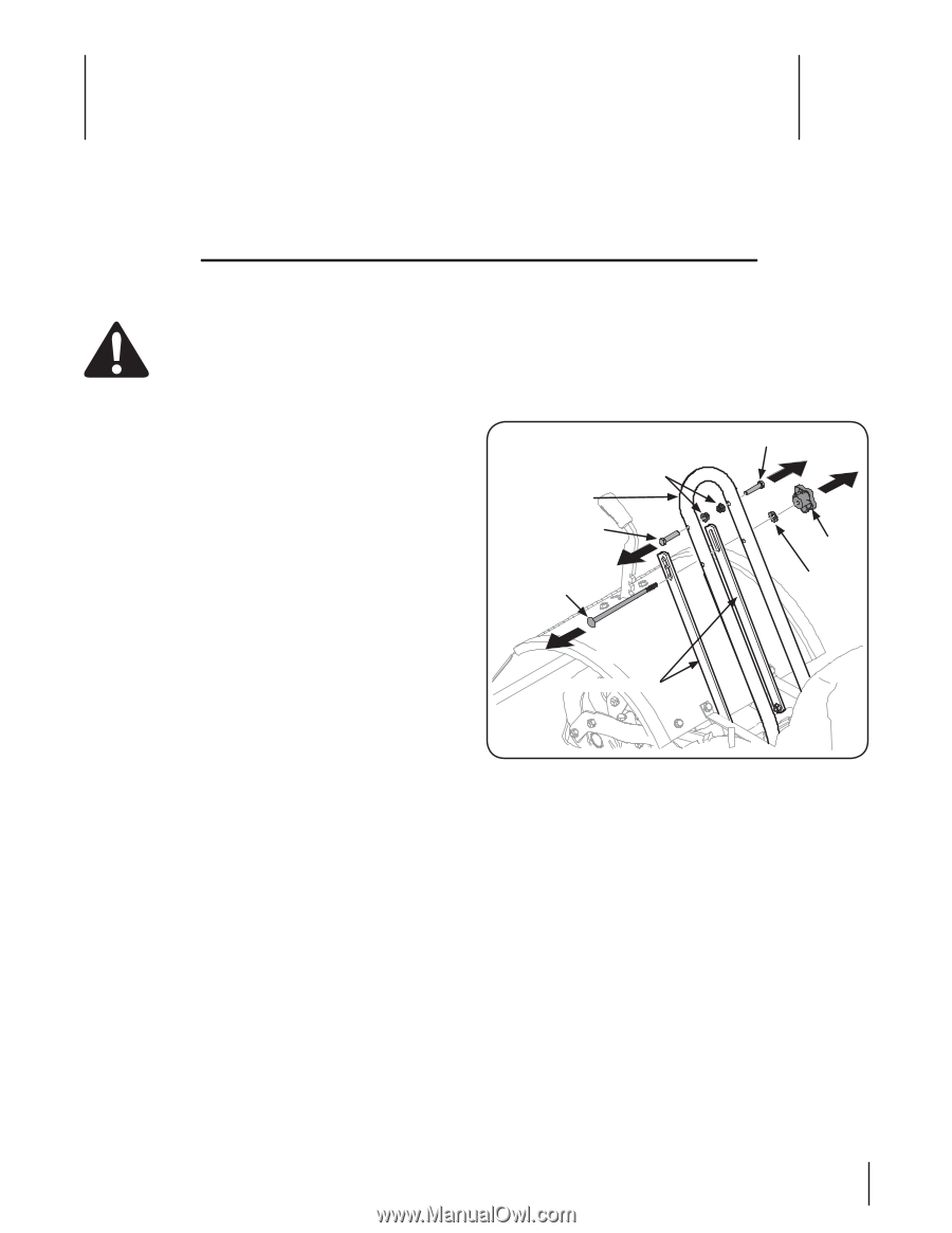
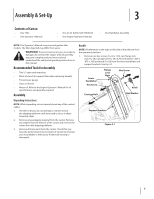
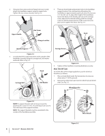
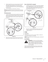
Assembly & Set-Up 3 Contents of Carton • One Tiller • One Operator's Manual • One 20 oz. Bottle SAE 10W30 Oil • One Engine Operator's Manual • One Handlebar Assembly NOTE: This Operator's Manual covers several garden tiller models. The tiller depicted may differ from yours. WARNING! To prevent personal injury or property damage, do not start the engine until all assembly steps are complete and you have read and understand the safety and operating instructions in this manual. Recommended Tools for Assembly • Two 1⁄2" open-end wrenches • Block of wood (to support tiller when removing wheels) • Tire pressure gauge • Clean oil funnel • Motor oil. Refer to the Engine Operator's Manual for oil specifications and quantity required. Assembly Unpacking Instructions NOTE: While unpacking, do not severely bend any of the control cables. 1. The tiller is heavy, do not attempt to remove it from the shipping platform until instructed to do so in these Assembly steps. 2. Remove any packaging material from the carton. Remove any staples from the bottom of the carton and remove the carton from the shipping platform. 3. Remove all loose parts from the carton. Check that you have the items listed in the Contents of Carton list (contact your local dealer or the factory if items are missing or damaged). Handle NOTE: All references to the right or left side of the tiller are from the operator's position. 1. Remove two hex screws (5⁄16-18 x 1.50), two flange lock nuts (5⁄16-18), carriage bolt (5⁄16-18 x 6.75), bell washer (.326 x .875 x .145) and knob (5⁄16-18) from the lower handlebar and support brackets. See Fig. 3-1. Lower Handlebar Hex Screw Flange Lock Nuts Hex Screw Knob Carriage Bolt Bell Washer Support Brackets Figure 3-1 7
-
 1
1 -
 2
2 -
 3
3 -
 4
4 -
 5
5 -
 6
6 -
 7
7 -
 8
8 -
 9
9 -
 10
10 -
 11
11 -
 12
12 -
13
-
14
-
15
-
16
-
17
-
18
-
19
-
20
-
21
-
22
-
23
-
24
-
25
-
26
-
27
-
28
-
29
-
30
-
31
-
32
-
33
-
34
-
35
-
36
-
37
-
38
-
39
-
40
-
41
-
42
-
43
-
44
-
45
-
46
-
47
-
48
 |
 |