Troy-Bilt Pro-Line FRT Operation Manual - Page 25
Replacing a Single Tine, Removing a Tine Assembly
 |
View all Troy-Bilt Pro-Line FRT manuals
Add to My Manuals
Save this manual to your list of manuals |
Page 25 highlights
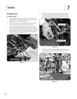
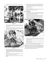
Replacing a Single Tine 1. Remove the two screws and nuts that attach a single tine to the tine holder. If needed, use penetrating oil to help free the nuts. See Fig. 7-9. Removing a Tine Assembly 1. If removing both tine assemblies, mark them "left" and "right" before removal. Doing so will help ensure that the assemblies are reinstalled on the correct sides of the tiller. 2. Remove the screw and locknut that secure the tine assembly to the tine shaft. See Fig. 7-10. Pull the tine assembly off the shaft. If necessary, use a rubber mallet to tap the tine assembly outward. Cutting Edge Figure 7-9 2. When installing a single tine, be sure to position it so that its cutting edge will enter the soil first as the tiller moves forward. Cutting Edge Figure 7-10 3. Before reinstalling the tine assembly, inspect the tine shaft for rust, rough spots or burrs and file or sand as needed. Then apply a thin coat of grease to the shaft. 4. Install each tine assembly so that the cutting edge of the tines will enter the soil first when the tiller moves forward. Secure the tine assembly to the tine shaft using the screw and locknut previously removed. Tighten securely. Section 7 - Service 25
-
 1
1 -
2
-
3
-
4
-
5
-
6
-
7
-
8
-
9
-
10
-
11
-
12
-
13
-
14
-
15
-
16
-
17
-
18
-
19
-
 20
20 -
 21
21 -
 22
22 -
 23
23 -
 24
24 -
 25
25 -
 26
26 -
 27
27 -
 28
28
 |
 |
