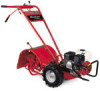
Troy-Bilt Pro-Line FRT Operation Manual - Page 8
Handlebar Cross Brace
 |
View all Troy-Bilt Pro-Line FRT manuals
Add to My Manuals
Save this manual to your list of manuals |
Page 8 highlights
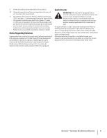
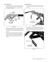
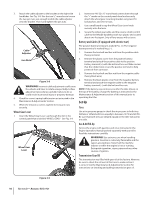
3. Gently lift the handlebar (do not overstretch the attached cable) and place the handlebar cross-brace in front of the curved height adjustment bracket. See Fig. 3-2. 6. On electric start machines, reattach the height adjustment bracket. Tighten both screws securely. Make sure the handlebar cross-brace is under the bracket. Keyed Washer 7. Move the handlebars up or down to align the threaded hole in the cross brace with one of the four slots in the curved height adjustment bracket. Place the keyed washer on the flange head height adjustment screw with the raised edges of the washer facing down. See Fig. 3-2. Mounting Tabs shown for clarity. 8. Thread the height adjustment screw into the hole in the handlebar cross-brace, making sure that the raised keys on the washer fit into the slot on the height adjustment bracket. Tighten the height adjustment screw securely. Next, securely tighten the two screws and nuts in the ends of the handlebar. 9. To remove the tiller from its shipping platform, first Adjustment Screw carefully unwrap the wheel gear cable with the attached lever from around the chassis. Move the Wheel Gear Lever to the DISENGAGE position, this allows the wheels to rotate Height Adjustment Bracket Handlebar Cross Brace freely. See Fig. 3-4. Use the handlebars to roll the tiller off the platform. Figure 3-2 4. With the forward clutch cable on the inside of the handlebar (See Fig, 3-3), position the handlebar ends on the outside of the two mounting tabs shown in Fig. 3-2 on the transmission top cover. Wheel Gear Lever Forward Clutch Cable Lock Nuts Figure 3-4 NOTE: Use the DISENGAGE position only when the engine is not running. Before starting the engine, the Wheel Gear Lever must be placed in the ENGAGE position (see the Operation Section for details). Figure 3-3 NOTE: The curved handlebar height adjustment bracket appears as shown in Fig. 3-2 for non-electric start tillers. For electric start machines, the bracket is loosened and moved to one side. 5. Loosely attach the handlebars to the mounting tabs with two 3⁄8-16 x 1" screws (heads of screws go to inside of tabs), 3⁄8" flat washers and 3⁄8"-16 lock nuts. See Fig. 3-3. 8 Section 3- Assembly & Set-Up
-
 1
1 -
2
-
 3
3 -
 4
4 -
 5
5 -
 6
6 -
 7
7 -
 8
8 -
 9
9 -
 10
10 -
 11
11 -
 12
12 -
 13
13 -
14
-
15
-
16
-
17
-
18
-
19
-
20
-
21
-
22
-
23
-
24
-
25
-
26
-
27
-
28
 |
 |
