Troy-Bilt TB R18 Operation Manual - Page 5
Assembly & Set-Up
 |
View all Troy-Bilt TB R18 manuals
Add to My Manuals
Save this manual to your list of manuals |
Page 5 highlights
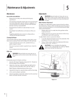
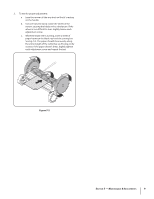
Assembly & Set-Up Contents of Crate • One Upper Handle • Six Carriage Bolts • One Grass Catcher (TB R18 Only) • Two Mid Handles • Six Wing Knobs • One Operator's Manual Mower Set-Up Attaching the Handle 1. Secure the upper handle to the mid handles with two carriage bolts, two saddle washers and two wing knobs. See Fig. 3-1. 3 • One Lower Handle • Six Saddle Washers • One Product Registration Card Figure 3-1 2. Securethehandleassembledinstep1tothelowerhandlewith four carriage bolts, four saddle washers and four wing knobs. See Fig. 3-2. 3. Position the complete handle assembly over the studs on the rear of the mower frame. See Fig. 3-3. Figure 3-2 Figure 3-3 5
-
 1
1 -
 2
2 -
 3
3 -
 4
4 -
 5
5 -
 6
6 -
 7
7 -
 8
8 -
 9
9 -
 10
10 -
 11
11 -
12
-
13
-
14
-
15
-
16
-
17
-
18
-
19
-
20
-
21
-
22
-
23
-
24
 |
 |

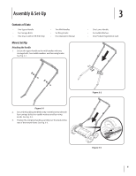
Mower Set-Up
Attaching the Handle
Secure the upper handle to the mid handles with two
1.
carriage bolts, two saddle washers
and two wing knobs.
See Fig. 3-1.
Secure the handle assembled in step 1 to the lower handle with
2.
four carriage bolts, four saddle washers and four wing
knobs. See Fig. 3-2.
Position the complete handle assembly over the studs on the
3.
rear of the mower frame. See Fig. 3-3.
Figure 3-2
Figure 3-3
Figure 3-1
Contents of Crate
One Upper Handle
•
Two Mid Handles
•
One Lower Handle
•
Six Carriage Bolts
•
Six Wing Knobs
•
Six Saddle Washers
•
One Grass Catcher (TB R18 Only)
•
One Operator’s Manual
•
One Product Registration Card
•
Assembly & Set-Up
3
5