Troy-Bilt TB516 Operation Manual - Page 4

Specifications, Maintenance And Repair Instructions, Optional Accessory, Cleaning And Storage - replacement blade

Page 4 highlights

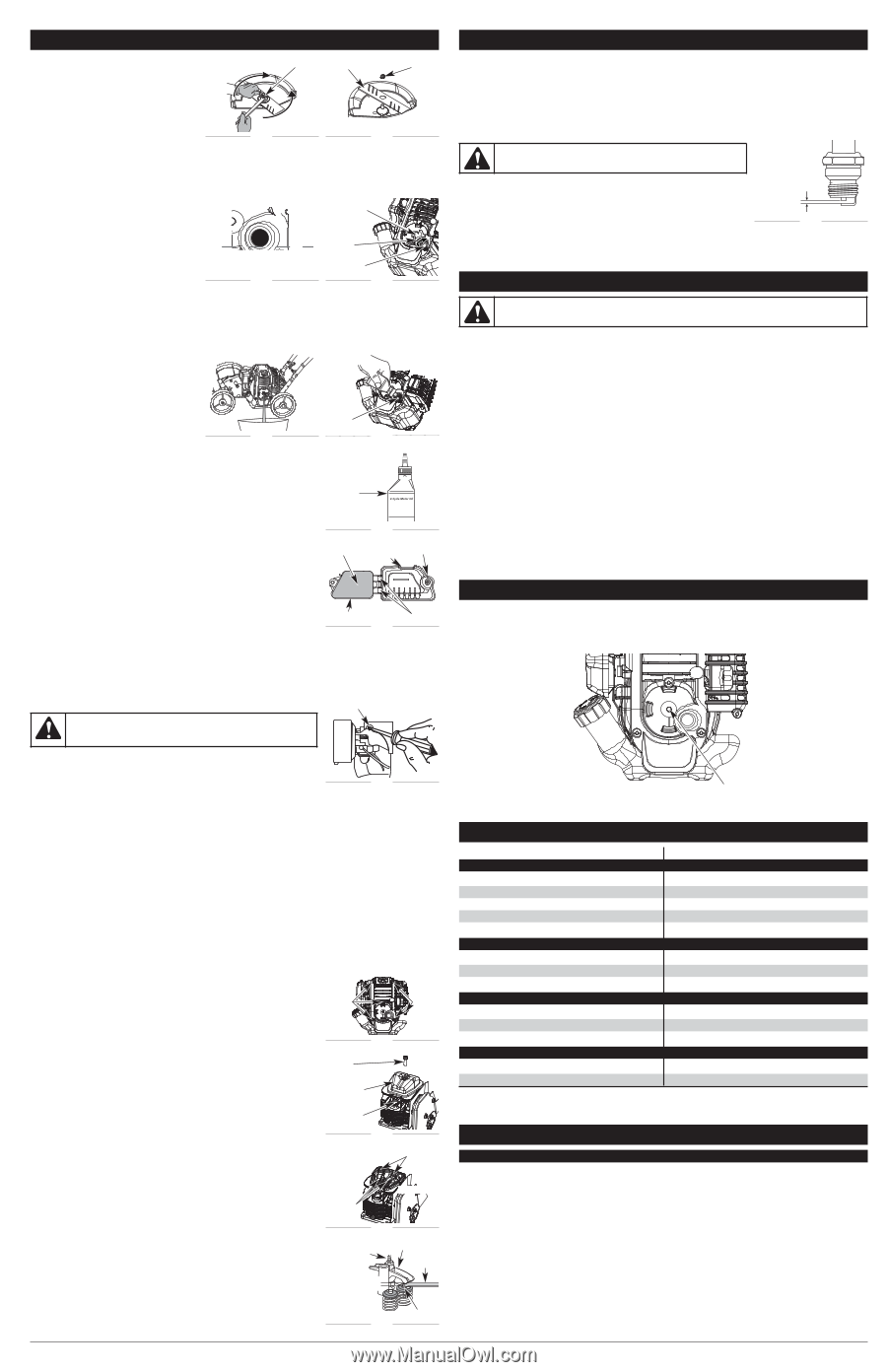
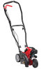
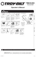
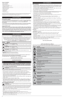
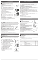
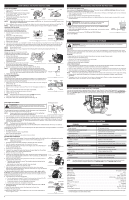
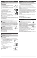
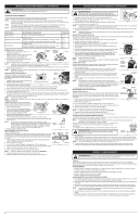
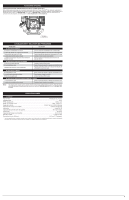
MAINTENANCE AND REPAIR INSTRUCTIONS BLADE REPLACEMENT 1. Place the 5/16" Allen wrench in the spindle hole (Fig. 11). Tighten Spindle Hole Edger Blade Nut 2. While holding the Allen wrench in place, loosen the nut with a 15/16" wrench by turning it counterclockwise (Fig. 11). 3. Remove the nut and blade. Keep the nut for new blade installation. Loosen 4. Install the new blade and nut (Fig. 12). Fig. 11 Fig. 12 NOTE: Make sure the blade edges are facing the proper direction (Fig. 12). The unit will not function correctly if the edger blade is installed backward. 5. While holding the Allen wrench in the spindle hole, tighten the nut by turning the wrench clockwise until tight (Fig. 11). NOTE: Make sure that the blade stays flat and centered against the output shaft throughout installation. CHECKING THE OIL LEVEL The importance of checking and maintaining the proper oil level in the crankcase cannot be overemphasized. Check oil before each use: Oil Fill Plug 1. Stop the engine and allow oil to drain into the crankcase. 2. Place unit on a flat, level surface. O-Ring 3. Keep dirt, grass clippings and other debris out of the engine. Clean the area around the dipstick before removing it. 4. Remove the oil fill plug. Oil Max Fill Line Fig. 13 Oil Fill Hole Fig. 14 5. Look into the oil fill hole, use a flashlight if needed. The oil should be just touching the inner most thread (Fig. 13). 6. If the oil level is not touching the inner most thread on the oil fill hole, add a small amount of oil to the oil fill hole and recheck (Fig. 16). Repeat this procedure until the oil level reaches the inner most thread on the oil fill hole. NOTE: Do not overfill the unit. NOTE: Make sure the O-ring is in place on the oil fill plug when checking and changing the oil (Fig. 14). CHANGING THE OIL Change the oil per the maintenance schedule. Change the oil while the engine is still warm. The oil will flow freely and carry away more impurities. 1. Remove the oil fill plug. 2. Pour the oil out of the oil fill hole and into a container by tipping the unit to a vertical position (Fig. 15). Allow ample time for complete drainage. Oil Fill Hole 3. Wipe up any oil residue on the unit and clean up any oil that may have spilled. Dispose of the oil according to federal, state and local regulations. Fig. 15 Fig. 16 4. Refill the crankcase with 3.04 fl.oz. (90 ml) of SAE 30 SF, SG, SH oil. NOTE: Use the bottle and spout saved from initial use to measure the correct amount of oil. The top of the label on the bottle measures approximately 3.04 fl.oz. (90 ml) (Fig. 17). Check the level, See Checking the Oil Level. If the level is low, add a small amount of oil and recheck. Do not overfill (Fig. 13). Fill Level 5. Replace the oil fill plug. AIR FILTER MAINTENANCE Cleaning the Air Filter Clean and re-oil the air filter per the maintenance schedule. It is an important item to maintain. Failure to maintain the air filter properly can result in poor performance or can cause permanent damage to the engine. 1. Open the air filter cover. Unscrew the knob on the left side of the cover. Swing the cover out (Fig. 18). Air Filter Fig. 17 Air Filter Cover Knob 2. Remove the air filter (Fig. 18). 3. Wash the filter in detergent and water. Rinse the filter thoroughly and allow it to dry. 4. Apply enough clean SAE 30 motor oil to lightly coat the filter. Back Plate Hooks 5. Squeeze the filter to spread and remove excess oil. Fig. 18 6. Replace the filter (Fig. 18). NOTE: Operating the unit without the air filter, will VOID the warranty. 7. Make sure the back plate is correctly positioned (Fig. 18). 8. Swing the air filter cover closed and tighten the knob (Fig. 18). MAINTENANCE AND REPAIR INSTRUCTIONS REPLACING THE SPARK PLUG Use a replacement Champion® #RDZ4H spark plug. The correct air gap is 0.025 in. (0.635 mm). Remove the plug and check its condition per the maintenance schedule. 1. Stop the engine and allow it to cool. Remove the six (6) screws on the back of the engine cover with a Flat-head or T-25 screwdriver (Fig. 20). 2. Grasp the plug wire firmly and pull the cap from the spark plug. 3. Clean dirt from around the spark plug. Remove the spark plug from the cylinder head by turning a 5/8 in. socket counterclockwise. WARNING: Do not sand blast, scrape or clean spark plug electrodes. Grit in the engine could damage the cylinder. 4. Replace cracked, fouled or dirty spark plug. Set the air gap at 0.025 in. (0.635 mm) using a feeler gauge (Fig. 24). 5. Install a correctly-gapped spark plug in the cylinder head. Turn the 5/8 in. socket clockwise until snug. If using a torque wrench torque to: 110-120 in.•lb. (12.3-13.5 N•m) Do not over-tighten. 0.025 in. (0.635 mm) Fig. 24 CLEANING AND STORAGE WARNING: To avoid serious personal injury, always turn the unit off and allow it to cool before cleaning or maintaining it. CLEANING Use a small brush to clean off the outside of the unit. Do not use strong detergents. Household cleaners that contain aromatic oils such as pine and lemon, and solvents such as kerosene, can damage plastic housing or handle. Wipe off any moisture with a soft cloth. STORAGE • Never store the unit with fuel in the tank where fumes may reach an open flame or spark. • Allow the engine to cool before storing. • Lock up the unit to prevent unauthorized use or damage. • Store the unit in a dry, well-ventilated area. • Store the unit out of the reach of children. LONG TERM STORAGE 1. Drain all gasoline from the gas tank into a container. Do not use gas that has been stored for more than 30 days. Dispose of the old gasoline in accordance to federal, state and local regulations. 2. Start the engine and allow it to run until it stalls. This ensures that all gasoline has been drained from the carburetor. 3. Allow the engine to cool. Remove the spark plug and put 5 drops of high quality motor oil into the cylinder. Pull the starter rope slowly to distribute the oil. Reinstall the spark plug. NOTE: Remove the spark plug and drain all of the oil from the cylinder before attempting to start the edger after storage. 4. Change the oil, referring to Changing the Oil. Dispose of the old oil in accordance to federal, state and local regulations. 5. Thoroughly clean the unit and inspect for any loose or damaged parts. Repair or replace damaged parts and tighten loose screws, nuts or bolts. The unit is ready for storage. OPTIONAL ACCESSORY ELECTRIC STARTER AND POWER START BIT™ FEATURES This unit can be started with an optional Electric Starter or Power Start Bit™ (Items Sold Separately!). If choosing to start the unit using one of these features or have questions, please contact your local retailer or call 1-800-828-5500 in the U.S. (1-800-668-1238 in Canada) for more information and purchasing. You may also go to www.troybilt.com or www.troybilt.ca. IDLE SPEED ADJUSTMENT WARNING: The blade may spin during idle speed adjustments. Wear protective clothing and observe all safety instructions to prevent serious personal injury. Idle Adjustment Screw The idle speed of the engine is adjustable. An idle adjustment screw is between the air filter cover and the engine starter housing (Fig. 19). NOTE: Careless adjustments can seriously damage your unit. An authorized service dealer should make carburetor adjustments. Fig. 19 If, after checking the fuel and cleaning the air filter, the engine still will not idle, adjust the idle speed screw as follows: 1. Start the engine and let it run at a high idle for a minute to warm up. Refer to Starting and Stopping Instructions. 2. Release the throttle lever and let the engine idle. If the engine stops, insert a small Phillips in between the air filter cover and the engine cover (Fig. 19). Turn the idle speed screw in, clockwise, 1/8 of a turn at a time (as needed) until the engine idles smoothly. NOTE: The blade should not rotate when the engine idles. 3. If the blade rotates when the engine idles, turn the idle speed screw counterclockwise 1/8 of a turn at a time (as needed), to reduce idle speed. Checking the fuel, cleaning the air filter, and adjusting the idle speed should solve most engine problems. If not and all of the following are true: • the engine will not idle • the engine hesitates or stalls on acceleration • there is a loss of engine power Have the carburetor adjusted by an authorized service dealer. ROCKER ARM CLEARANCE This requires disassembly of the engine. If unsure or unqualified to perform this, take the unit to an authorized service center. NOTE: Inspect the valve to rocker arm clearance with a feeler gauge per the maintenance schedule. • The engine must be cold when checking or adjusting the valve clearance. View of the Rear Engine Cover • This task should be performed inside, in a clean, dust free area. 1. Remove the six (6) screws on the back of the engine cover with a Flat-head or T- Screws 25 Torx screwdriver (Fig. 20). Screws 2. Disconnect the spark plug wire. 3. Clean dirt from around the spark plug. Remove the spark plug from the cylinder head by turning a 5/8 in. socket counterclockwise. Fig. 20 4. Remove the engine cover (Fig. 20). 5. Clean dirt from around the rocker arm cover. Remove the screw holding the rocker Screw arm cover with a large flat blade screwdriver or Torx T-25 bit (Fig. 21). Remove the rocker arm cover and gasket. 6. Pull the starter rope slowly to bring the piston to the top of its travel, (known as Rocker Arm Cover top dead center). Check that: • The piston is at the top of its travel. This should be done by looking into the spark plug hole. (Fig. 21) Spark Plug Hole • Both rocker arms move freely, and both valves are closed If these statements are not true, repeat this step. Fig. 21 7. Slide the feeler gauge between the rocker arm and the valve return spring. Measure the clearance between the valve stem and rocker arm (Fig. 23). Measure both the intake and exhaust valves. INTAKE Adjusting Nuts The recommended clearance for both intake and exhaust is .003 - .006 in. (.076 - 0.152 mm). Use a standard automotive .005 in. (0.127 mm) feeler gauge. The feeler gauge should slide between the rocker arm and valve stem with a slight amount of resistance, without binding (Fig. 23). 8. If the clearance is not within specification: a. Turn the adjusting nut using a 5/16 inch (8 mm) wrench or nut driver (Fig. 23). • To increase clearance, turn the adjusting nut counterclockwise. Rocker Arms EXHAUST Fig. 22 • To decrease clearance, turn the adjusting nut clockwise. b. Recheck both clearances, and adjust as necessary. 9. Reinstall the rocker arm cover using a new gasket. Torque the screw to 20-30 in•lb (2.2-3.4 N•m). 10. Check the spark plug and reinstall. See Replacing the Spark Plug. Exhaust Adjusting Nut 0.003-0.006 in. (0.076-0.152 mm) Rocker Arm Feeler Gauge 11. Replace the spark plug wire. 12. Reinstall the engine cover. Check alignment of the cover before tightening the screws. Tighten screws. Valve Stem Fig. 23 4 Electric Start Feature TROUBLESHOOTING PROBLEM THE ENGINE WILL NOT START Empty fuel tank Primer bulb was not pressed enough Old fuel (over 30 days) Fouled spark plug Cold weather start lever is in closed position THE ENGINE WILL NOT IDLE Air filter is plugged Old fuel Improper idle speed THE ENGINE WILL NOT ACCELERATE Old fuel Blade bound with dirt or grass Dirty air filter THE ENGINE LACKS POWER OR STALLS Old fuel Fouled spark plug SOLUTION Fill fuel tank with fuel Press the primer bulb 10 times or until fuel is visible Drain fuel tank and add fresh fuel Replace or clean the spark plug Move cold weather start lever to open position Replace or clean the air filter Drain gas tank and add fresh fuel Adjust according to the Idle Speed Adjustment section Drain gas tank and add fresh fuel Stop the engine and clean the blade Clean or replace the air filter Drain gas tank and add fresh fuel Replace or clean the spark plug NOTE: For repairs beyond the minor adjustments listed above, locate your nearest authorized service center by calling the Customer Support Department at 1-800-828-5500 (U.S.) or 1-800-668-1238 (Canada). SPECIFICATIONS UNIT* Engine Type Air-Cooled, 4-Cycle Displacement 29 cc Operating RPM 6,800+ rpm Idle Speed RPM 2,800 - 4,200 rpm Valve clearance 0.003-0.006 in. (0.076-0.152 mm) Spark Plug Gap 0.025 in. (0.635 mm) Lubrication SAE 30 Oil Crankcase Oil Capacity 3.04 oz (90 ml) Fuel Unleaded Fuel Tank Capacity 14 oz (414 ml) Unit Weight 24.7 lbs. (11.2 kg) Cutting Depth (maximum 1.75 in. (44.5 mm) * All specifications are based on the latest product information available at the time of printing. We reserve the right to make changes at any time without notice.

  • 1
  • 2
  • 3
  • 4
  • 5
  • 6
  • 7
  • 8
  • 9
  • 10
  • 11
  • 12

REPLACING THE SPARK PLUG
Use a replacement
Champion® #RDZ4H
spark plug. The correct air gap is
0.025 in. (0.635 mm)
. Remove the plug
and check its condition per the maintenance schedule.
1.
Stop the engine and allow it to cool. Remove the six (6) screws on the back of the engine cover with a Flat-head or
T-25 screwdriver (Fig. 20).
2.
Grasp the plug wire firmly and pull the cap from the spark plug.
3.
Clean dirt from around the spark plug. Remove the spark plug from the cylinder head by turning a 5/8 in. socket
counterclockwise.
4.
Replace cracked, fouled or dirty spark plug. Set the air gap at
0.025 in. (0.635
mm)
using a feeler gauge (Fig. 24).
5.
Install a correctly-gapped spark plug in the cylinder head. Turn the 5/8 in. socket
clockwise until snug.
If using a torque wrench torque to:
110-120 in.•lb. (12.3-13.5 N•m)
Do not over-tighten.
PROBLEM
SOLUTION
IDLE SPEED ADJUSTMENT
The idle speed of the engine is adjustable. An idle adjustment screw is between the
air filter cover and the engine starter housing (Fig. 19).
NOTE:
Careless adjustments can seriously damage your unit. An authorized
service dealer should make carburetor adjustments.
If, after checking the fuel and cleaning the air filter, the engine still will not idle, adjust the idle speed screw as follows:
1.
Start the engine and let it run at a high idle for a minute to warm up. Refer to
Starting and Stopping Instructions
.
2.
Release the throttle lever and let the engine idle. If the engine stops, insert a small Phillips in between the air filter
cover and the engine cover (Fig. 19). Turn the idle speed screw in, clockwise, 1/8 of a turn at a time (as needed)
until the engine idles smoothly.
NOTE:
The blade should not rotate when the engine idles.
3.
If the blade rotates when the engine idles, turn the idle speed screw counterclockwise 1/8 of a turn at a time (as
needed), to reduce idle speed.
Checking the fuel, cleaning the air filter, and adjusting the idle speed should solve most engine problems. If not and all
of the following are true:
the engine will not idle
the engine hesitates or stalls on acceleration
there is a loss of engine power
Have the carburetor adjusted by an authorized service dealer.
ROCKER ARM CLEARANCE
This requires disassembly of the engine. If unsure or unqualified to perform this, take the unit to an authorized service center.
NOTE:
Inspect the valve to rocker arm clearance with a feeler gauge per the
maintenance schedule.
The engine must be cold when checking or adjusting the valve clearance.
This task should be performed inside, in a clean, dust free area.
1.
Remove the six (6) screws on the back of the engine cover with a Flat-head or T-
25 Torx screwdriver (Fig. 20).
2.
Disconnect the spark plug wire.
3.
Clean dirt from around the spark plug. Remove the spark plug from the cylinder
head by turning a 5/8 in. socket counterclockwise.
4.
Remove the engine cover (Fig. 20).
5.
Clean dirt from around the rocker arm cover. Remove the screw holding the rocker
arm cover with a large flat blade screwdriver or Torx T-25 bit (Fig. 21). Remove the
rocker arm cover and gasket.
6.
Pull the starter rope slowly to bring the piston to the top of its travel, (known as
top dead center). Check that:
The piston is at the top of its travel. This should be done by looking into the
spark plug hole. (Fig. 21)
Both rocker arms move freely, and both valves are closed
If these statements are not true, repeat this step.
7.
Slide the feeler gauge between the rocker arm and the valve return spring.
Measure the clearance between the valve stem and rocker arm (Fig. 23). Measure
both the intake and exhaust valves.
The recommended clearance for both intake and exhaust is
.003 – .006 in. (.076 –
0.152 mm)
. Use a standard automotive .005 in. (0.127 mm) feeler gauge. The feeler
gauge should slide between the rocker arm and valve stem with a slight amount of
resistance, without binding (Fig. 23).
8.
If the clearance is not within specification:
a.
Turn the adjusting nut using a 5/16 inch (8 mm) wrench or nut driver (Fig. 23).
To increase clearance, turn the adjusting nut counterclockwise.
To decrease clearance, turn the adjusting nut clockwise.
b.
Recheck both clearances, and adjust as necessary.
9.
Reinstall the rocker arm cover using a new gasket. Torque the screw to
20–30
in•lb (2.2–3.4 N•m)
.
10. Check the spark plug and reinstall. See
Replacing the Spark Plug
.
11. Replace the spark plug wire.
12. Reinstall the engine cover. Check alignment of the cover before tightening the
screws. Tighten screws.
UNIT*
Engine Type. . . . . . . . . . . . . . . . . . . . . . . . . . . . . . . . . . . . . . . . . . . . . . . . . . . . . . . . . . . . . . . . . . . . . Air-Cooled, 4-Cycle
Displacement . . . . . . . . . . . . . . . . . . . . . . . . . . . . . . . . . . . . . . . . . . . . . . . . . . . . . . . . . . . . . . . . . . . . . . . . . . . . . . . 29 cc
Operating RPM
. . . . . . . . . . . . . . . . . . . . . . . . . . . . . . . . . . . . . . . . . . . . . . . . . . . . . . . . . . . . . . . . . . . . . . . . 6,800+ rpm
Idle Speed RPM . . . . . . . . . . . . . . . . . . . . . . . . . . . . . . . . . . . . . . . . . . . . . . . . . . . . . . . . . . . . . . . . . . . 2,800 - 4,200 rpm
Valve clearance
. . . . . . . . . . . . . . . . . . . . . . . . . . . . . . . . . . . . . . . . . . . . . . . . . . . . . . 0.003–0.006 in. (0.076–0.152 mm)
Spark Plug Gap . . . . . . . . . . . . . . . . . . . . . . . . . . . . . . . . . . . . . . . . . . . . . . . . . . . . . . . . . . . . . . . . . 0.025 in. (0.635 mm)
Lubrication. . . . . . . . . . . . . . . . . . . . . . . . . . . . . . . . . . . . . . . . . . . . . . . . . . . . . . . . . . . . . . . . . . . . . . . . . . . . . SAE 30 Oil
Crankcase Oil Capacity
. . . . . . . . . . . . . . . . . . . . . . . . . . . . . . . . . . . . . . . . . . . . . . . . . . . . . . . . . . . . . . . 3.04 oz (90 ml)
Fuel . . . . . . . . . . . . . . . . . . . . . . . . . . . . . . . . . . . . . . . . . . . . . . . . . . . . . . . . . . . . . . . . . . . . . . . . . . . . . . . . . . . Unleaded
Fuel Tank Capacity. . . . . . . . . . . . . . . . . . . . . . . . . . . . . . . . . . . . . . . . . . . . . . . . . . . . . . . . . . . . . . . . . . . . 14 oz (414 ml)
Unit Weight. . . . . . . . . . . . . . . . . . . . . . . . . . . . . . . . . . . . . . . . . . . . . . . . . . . . . . . . . . . . . . . . . . . . . . . 24.7 lbs. (11.2 kg)
Cutting Depth (maximum) . . . . . . . . . . . . . . . . . . . . . . . . . . . . . . . . . . . . . . . . . . . . . . . . . . . . . . . . . . . 1.75 in. (44.5 mm)
SPECIFICATIONS
*
All specifications are based on the latest product information available at the time of printing. We reserve the right
to make changes at any time without notice.
4
ELECTRIC STARTER AND POWER START BIT™ FEATURES
This unit can be started with an optional Electric Starter or Power Start Bit™ (Items Sold Separately!). If choosing to
start the unit using one of these features or have questions, please contact your local retailer or call
1-800-828-5500
in
the U.S. (
1-800-668-1238
in Canada) for more information and purchasing. You may also go to
www.troybilt.com
or
www.troybilt.ca
.
Electric Start
Feature
WARNING:
Do not sand blast, scrape or clean spark plug
electrodes. Grit in the engine could damage the cylinder.
Fig. 19
Idle Adjustment Screw
Fig. 20
Fig. 21
Screws
Fig. 22
MAINTENANCE AND REPAIR INSTRUCTIONS
Fig. 23
WARNING:
The blade may spin during idle speed adjustments.
Wear protective clothing and observe all safety instructions to prevent
serious personal injury.
Fig. 24
0.025 in.
(0.635 mm)
Screws
View of the Rear
Engine Cover
Screw
Rocker
Arm Cover
Spark
Plug Hole
Adjusting
Nuts
INTAKE
EXHAUST
Rocker
Arms
0.003–0.006 in.
(0.076–0.152 mm)
Feeler
Gauge
Exhaust
Adjusting Nut
Rocker Arm
Valve Stem
OPTIONAL ACCESSORY
Old fuel
Drain gas tank and add fresh fuel
Fouled spark plug
Replace or clean the spark plug
Old fuel
Drain gas tank and add fresh fuel
Blade bound with dirt or grass
Stop the engine and clean the blade
Dirty air filter
Clean or replace the air filter
Empty fuel tank
Fill fuel tank with fuel
Primer bulb was not pressed enough
Press the primer bulb 10 times or until fuel is visible
Old fuel (over 30 days)
Drain fuel tank and add fresh fuel
Fouled spark plug
Replace or clean the spark plug
Cold weather start lever is in closed position
Move cold weather start lever to open position
Air filter is plugged
Replace or clean the air filter
Old fuel
Drain gas tank and add fresh fuel
Improper idle speed
Adjust according to the
Idle Speed Adjustment
section
TROUBLESHOOTING
THE ENGINE WILL NOT START
THE ENGINE WILL NOT IDLE
THE ENGINE WILL NOT ACCELERATE
NOTE:
For repairs beyond the minor adjustments listed above, locate your nearest authorized service center by
calling the Customer Support Department at
1-800-828-5500
(U.S.) or
1-800-668-1238
(Canada).
THE ENGINE LACKS POWER OR STALLS
BLADE REPLACEMENT
1.
Place the 5/16” Allen wrench in the spindle
hole (Fig. 11).
2.
While holding the Allen wrench in place, loosen
the nut with a 15/16” wrench by turning it
counterclockwise (Fig. 11).
3.
Remove the nut and blade. Keep the nut for
new blade installation.
4.
Install the new blade and nut (Fig. 12).
NOTE:
Make sure the blade edges are facing the proper direction (Fig. 12). The unit will not function correctly if the
edger blade is installed backward.
5.
While holding the Allen wrench in the spindle hole, tighten the nut by turning the wrench clockwise until tight (Fig. 11).
NOTE:
Make sure that the blade stays flat and centered against the output shaft throughout installation.
CHECKING THE OIL LEVEL
The importance of checking and maintaining the
proper oil level in the crankcase cannot be
overemphasized. Check oil before each use:
1.
Stop the engine and allow oil to drain into the
crankcase.
2.
Place unit on a flat, level surface.
3.
Keep dirt, grass clippings and other debris out
of the engine. Clean the area around the
dipstick before removing it.
4.
Remove the oil fill plug.
5.
Look into the oil fill hole, use a flashlight if needed. The oil should be just touching the inner most thread (Fig. 13).
6.
If the oil level is not touching the inner most thread on the oil fill hole, add a small amount of oil to the oil fill hole
and recheck (Fig. 16). Repeat this procedure until the oil level reaches the inner most thread on the oil fill hole.
NOTE:
Do not overfill the unit.
NOTE:
Make sure the O-ring is in place on the oil fill plug when checking and changing the oil (Fig. 14).
CHANGING THE OIL
Change the oil per the maintenance schedule.
Change the oil while the engine is still warm. The
oil will flow freely and carry away more impurities.
1.
Remove the oil fill plug.
2.
Pour the oil out of the oil fill hole and into a
container by tipping the unit to a vertical
position (Fig. 15). Allow ample time for
complete drainage.
3.
Wipe up any oil residue on the unit and clean
up any oil that may have spilled. Dispose of
the oil according to federal, state and local regulations.
4.
Refill the crankcase with 3.04 fl.oz. (90 ml) of SAE 30 SF, SG, SH oil.
NOTE:
Use the bottle and spout saved from initial use to measure the correct
amount of oil. The top of the label on the bottle measures approximately
3.04 fl.oz. (90 ml) (Fig. 17). Check the level, See
Checking the Oil Level
. If the
level is low, add a small amount of oil and recheck. Do not overfill (Fig. 13).
5.
Replace the oil fill plug.
AIR FILTER MAINTENANCE
Cleaning the Air Filter
Clean and re-oil the air filter per the maintenance schedule. It is an important item to
maintain. Failure to maintain the air filter properly can result in poor performance or
can cause permanent damage to the engine.
1.
Open the air filter cover. Unscrew the knob on the left side of the cover. Swing the
cover out (Fig. 18).
2.
Remove the air filter (Fig. 18).
3.
Wash the filter in detergent and water. Rinse the filter thoroughly and allow it to
dry.
4.
Apply enough clean SAE 30 motor oil to lightly coat the filter.
5.
Squeeze the filter to spread and remove excess oil.
6.
Replace the filter (Fig. 18).
NOTE:
Operating the unit without the air filter, will
VOID
the warranty.
7.
Make sure the back plate is correctly positioned (Fig. 18).
8.
Swing the air filter cover closed and tighten the knob (Fig. 18).
Fig. 11
Fig. 12
Edger Blade
Nut
Fig. 13
Oil Max Fill Line
Fig. 15
Fig. 17
Fig. 18
Air Filter
Tighten
Loosen
Spindle
Hole
Oil Fill Plug
Fig. 14
O-Ring
Oil Fill Hole
Air Filter
Cover
Knob
Back Plate
Hooks
Fill Level
Fig. 16
Oil Fill
Hole
CLEANING
Use a small brush to clean off the outside of the unit. Do not use strong detergents. Household cleaners that contain
aromatic oils such as pine and lemon, and solvents such as kerosene, can damage plastic housing or handle. Wipe off
any moisture with a soft cloth.
STORAGE
Never store the unit with fuel in the tank where fumes may reach an open flame or spark.
Allow the engine to cool before storing.
Lock up the unit to prevent unauthorized use or damage.
Store the unit in a dry, well-ventilated area.
Store the unit out of the reach of children.
LONG TERM STORAGE
1.
Drain all gasoline from the gas tank into a container. Do not use gas that has been stored for more than 30 days.
Dispose of the old gasoline in accordance to federal, state and local regulations.
2.
Start the engine and allow it to run until it stalls. This ensures that all gasoline has been drained from the carburetor.
3.
Allow the engine to cool. Remove the spark plug and put 5 drops of high quality motor oil into the cylinder. Pull the
starter rope slowly to distribute the oil. Reinstall the spark plug.
NOTE:
Remove the spark plug and drain all of the oil from the cylinder before attempting to start the edger after storage.
4.
Change the oil, referring to
Changing the Oil
. Dispose of the old oil in accordance to federal, state and local
regulations.
5.
Thoroughly clean the unit and inspect for any loose or damaged parts. Repair or replace damaged parts and
tighten loose screws, nuts or bolts. The unit is ready for storage.
WARNING:
To avoid serious personal injury, always turn the unit off and allow it to cool before
cleaning or maintaining it.
CLEANING AND STORAGE