Troy-Bilt TB625 Operation Manual - Page 6
Assembly
 |
View all Troy-Bilt TB625 manuals
Add to My Manuals
Save this manual to your list of manuals |
Page 6 highlights
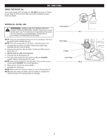
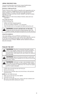
ASSEMBLY INSTALLING THE CUTTING HEAD SHIELD WARNING: To prevent serious personal injury, never operate the unit without the cutting head shield in place. Cutting Head Shield Use the following instructions if the cutting head shield is not installed. Use only the instructions that apply to the type of shaft and shield equipped with this unit. 1. Remove the wing nut and washer from the cutting head shield. 2. Insert the short tab (the one without a hole) on the mount bracket into the slot on the cutting head shield (Fig. 1). 3. Rotate the cutting head shield counterclockwise to align the hole on the cutting head shield with the hole on the mount bracket (Fig. 1). 4. Insert the square bolt into the hole underneath the cutting head shield (Fig. 2). Push the square bolt through the cutting head shield and mount bracket. 5. Put the washer onto the square bolt (Fig. 2). 6. Screw the wing nut onto the square bolt until the cutting head shield is firmly in place (Fig. 2). Cutting Head Shield Slot Fig. 1 INSTALLING AND ADJUSTING THE HANDLE Installing the Handle 1. Push the handle down onto the shaft housing (Fig. 3). The bolt hole in the handle should be to the right. 2. Insert the bolt into the bolt hole and push it through (Fig. 3). Tighten the bolt with a 3/8" socket, but do not tighten the bolt completely. 3. While holding the unit in the operating position (Fig. 14), move the handle to the location that provides the best grip. Place it a minimum of 6 inches (15.24 cm) from the end of the shaft grip (Fig. 3). 4. Tighten the bolt with a 3/8" socket until the handle is secure. Adjusting the Handle If the handle requires adjustment: 1. Loosen the bolt with a 3/8" socket (Fig. 3). 2. While holding the unit in the operating position (Fig. 14), move the handle to the location that provides the best grip. Place it a minimum of 6 inches (15.24 cm) from the end of the shaft grip (Fig. 3). 3. Tighten the bolt with a 3/8" socket until the handle is secure. Square Bolt Fig. 2 Shaft Grip Minimum 6 in. (15.24 cm) Bolt Fig. 3 Mount Bracket Mount Bracket Wing Nut Washer Handle Shaft Housing 6
-
 1
1 -
 2
2 -
 3
3 -
 4
4 -
 5
5 -
 6
6 -
 7
7 -
 8
8 -
 9
9 -
 10
10 -
 11
11 -
 12
12 -
13
-
14
-
15
-
16
-
17
-
18
-
19
-
20
-
21
-
22
-
23
-
24
-
25
-
26
-
27
-
28
-
29
-
30
-
31
-
32
-
33
-
34
-
35
-
36
-
37
-
38
-
39
-
40
 |
 |
