URC MRF-300 Owners Manual - Page 6
Installation, Step 1 - Set the RF ID - base
 |
View all URC MRF-300 manuals
Add to My Manuals
Save this manual to your list of manuals |
Page 6 highlights
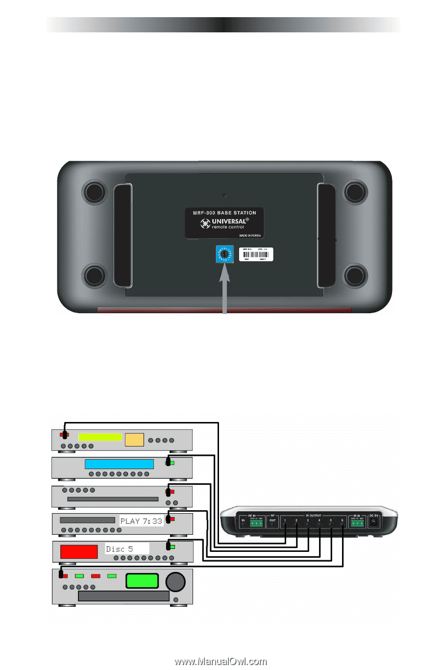
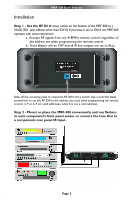
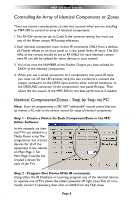
MRF-300 BASE STATION Installation Step 1 - Set the RF ID # rotary switch on the bottom of the MRF-300 to a VALID ID# (any address other than ID# 0). If you leave it set to ID# 0, the MRF-300 operates with some restrictions: a. Accepts RF signals from any 418MHZ remote control regardless of the address set when programming the remote control. b. Front Blaster will be OFF and all IR line outputs are set to ALL). Slide off the mounting plate to reveal the RF ID# rotary switch. Use a small flat blade screwdriver to set the RF ID# to the address you used when programming the remote control (1-9 or A-F are valid addresses, while 0 is not a valid address). Step 2 - Mount or place the MRF-300 conveniently and run flashers to each component's front panel sensor or connect the Line Out to a components rear panel IR Input. Page 3
-
 1
1 -
 2
2 -
 3
3 -
 4
4 -
 5
5 -
 6
6 -
 7
7 -
 8
8 -
 9
9 -
 10
10 -
 11
11 -
 12
12 -
13
-
14
-
15
-
16
 |
 |