URC MRF-300 Owners Manual - Page 8
Step 4 - Connect the Power Supply to the MRF-300., Step 5 - Power on the entire Audio/Video System
 |
View all URC MRF-300 manuals
Add to My Manuals
Save this manual to your list of manuals |
Page 8 highlights
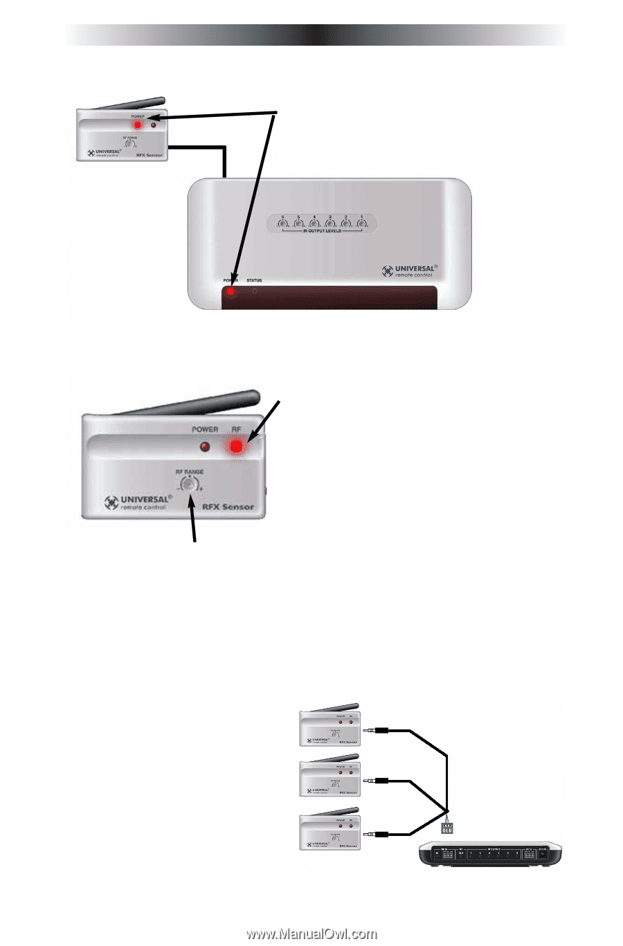
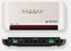
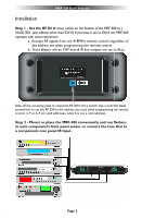
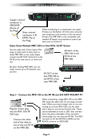
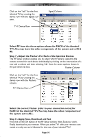
MRF-300 BASE STATION Step 4 - Connect the Power Supply to the MRF-300. The POWER LED's on both the RFX-150 and the MRF-300 should light up when the Power Supply is connected. Step 5 - Power on the entire Audio/Video System Test for RF Interference The RF LED lights when any RF signal is detected. If the RF LED flickers WITHOUT pressing a button on the remote control, you are receiving RF Interference and you must move the RFX-150 to another location.You can extend the wire up to 200' using standard CAT 5 cable. Place the RFX150 in another room or crawlspace to avoid interference. If you are restricted to a very small range of mounting locations and the LED flickers, reduce the range via the RF Range attenuator screw on the RFX-150. Step 6 - Mount the RFX-150 and adjust for Optimum Range Have someone press buttons on the remote control from the farthest distant operating position and adjust RF range screw and the angle of the RF-150 receiving antenna until the RF LED lights with every button push. If the desired range cannot be reliably maintained, you can opt to extend range by adding another RFX-150 RF Sensor in a location closer to the area where reception is unreliable. Each RFX-150 can provide coverage of 50 to 100 feet in normal conditions. Up to three RFX-150 Sensors can be connected. Each RFX-150 can be connected via up to 200 feet of standard CAT 5 cable to the MRF-300. Page 5
-
 1
1 -
2
-
 3
3 -
 4
4 -
 5
5 -
 6
6 -
 7
7 -
 8
8 -
 9
9 -
 10
10 -
 11
11 -
 12
12 -
 13
13 -
14
-
15
-
16
 |
 |