ViewSonic PJD6350 PJD6552LWS User Guide English - Page 13
Projector exterior view
 |
View all ViewSonic PJD6350 manuals
Add to My Manuals
Save this manual to your list of manuals |
Page 13 highlights
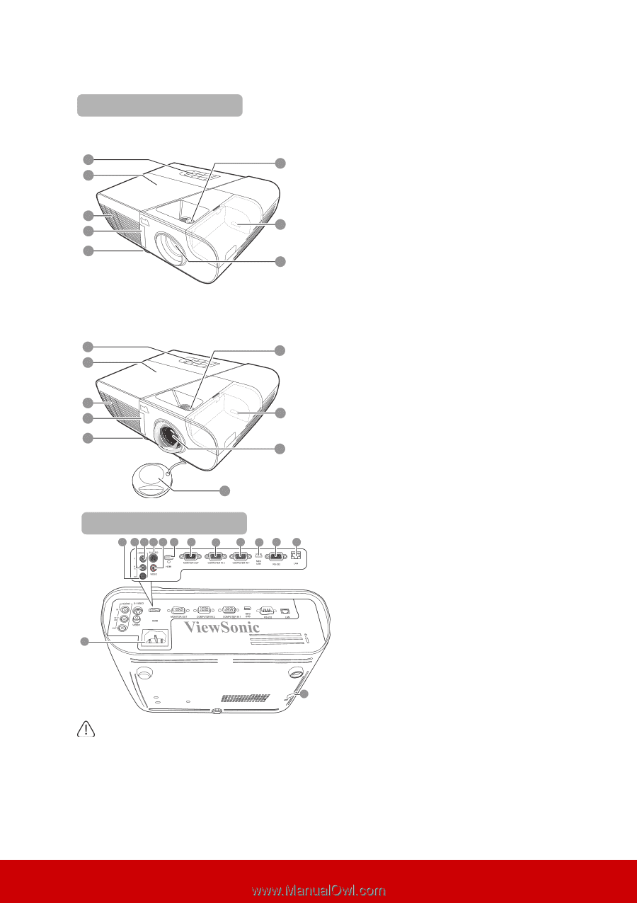
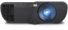
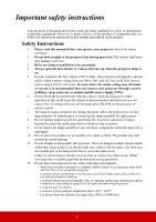
Projector exterior view Front/upper side PJD6350/PJD6352 PJD6550Lw/PJD6552Lw 1 6 2 3 4 7 5 8 PJD6351Ls/PJD6352Ls PJD6551Lws/PJD6552Lws 1 6 2 3 4 7 5 8 9 Rear/lower side 10 11 12 13 14 15 16 17 18 19 20 21 22 1. External control panel (See "Projector" on page 7 for details.) 2. Lamp cover 3. Vent (heated air exhaust) 4. Front IR remote sensor 5. Adjuster foot 6. Focus and Zoom rings (for PJD6255/PJD6350/PJD6555w/ PJD6550Lw) Focus ring (for PJD6385s/ PJD6351Ls/PJD6585ws/ PJD6551Lws) 7. HDMI/MHL port 8. Projection lens 9. Lens cap 10. Audio signal output socket 11. Audio signal input socket 2/ Microphone 12. Audio signal input socket 1 13. S-Video input socket 14. Video input socket 15. HDMI port 16. RGB signal output socket 17. RGB (PC)/Component video (YPbPr/YCbCr) signal input socket-2 18. RGB (PC)/Component video (YPbPr/YCbCr) signal input socket-1 19. Mini USB port 20. RS-232 control port 21. RJ45 LAN input port 22. AC power cord inlet 23. Security bar for anti-theft lock slot 23 Warning • THIS APPARATUS MUST BE EARTHED. • When installing the unit, incorporate a readily accessible disconnect device in the fixed wiring, or connect the power plug to an easily accessible socket-outlet near the unit. If a fault should occur during operation of the unit, operate the disconnect device to switch the power supply off, or disconnect the power plug. 6
-
 1
1 -
2
-
3
-
4
-
5
-
6
-
7
-
 8
8 -
 9
9 -
 10
10 -
 11
11 -
 12
12 -
 13
13 -
 14
14 -
 15
15 -
 16
16 -
 17
17 -
 18
18 -
19
-
20
-
21
-
22
-
23
-
24
-
25
-
26
-
27
-
28
-
29
-
30
-
31
-
32
-
33
-
34
-
35
-
36
-
37
-
38
-
39
-
40
-
41
-
42
-
43
-
44
-
45
-
46
-
47
-
48
-
49
-
50
-
51
-
52
-
53
-
54
-
55
-
56
-
57
-
58
-
59
-
60
-
61
-
62
-
63
-
64
-
65
-
66
-
67
-
68
-
69
-
70
-
71
-
72
-
73
-
74
-
75
-
76
-
77
-
78
-
79
-
80
-
81
-
82
-
83
-
84
-
85
-
86
-
87
-
88
-
89
-
90
-
91
-
92
-
93
-
94
-
95
 |
 |