ViewSonic VA550 Service Manual - Page 16
MPU1C25
 |
UPC - 766907390339
View all ViewSonic VA550 manuals
Add to My Manuals
Save this manual to your list of manuals |
Page 16 highlights
Service Manual VA550 THEORY OF CIRCUIT OPERATION ViewSonic Corporation Ng 0 R73 600 R77 .0 606 012 ici5 74.14 5015 741S14 13 1014 241.021/..N.0 NG V NC VOLE VSS SDA I ." .5 NC 900 11606) 011 2S R76 1114149 11.0 SC V, 0 l^10 OA 0 0 RI 330P 75 0200 II 15 4.14 WOI WOO ) R42 .7 75 0200) 206) 138 10 02 VLCD VLCD CND 6110 LO7 4.7 I, (1206) 117001 IK 000 C1213 REI 10 CO C105 82P R80 416 15 74 x0 z DO N4149 5V 1017 740.0 058 10 ' Ryyy 3 2.3K 10 1183 0906 R9.1 s CI SOV VS 1017 74H086 II 06 4,1000 1016 74X04053 740000 1.6 74104063 10 050/4015 c, GADDIN-7.8 CO SOD
-
 1
1 -
2
-
3
-
4
-
5
-
6
-
7
-
8
-
9
-
10
-
 11
11 -
 12
12 -
 13
13 -
 14
14 -
 15
15 -
 16
16 -
 17
17 -
 18
18 -
 19
19 -
 20
20 -
 21
21 -
22
-
23
-
24
-
25
-
26
-
27
-
28
-
29
-
30
-
31
-
32
-
33
-
34
-
35
-
36
-
37
-
38
-
39
-
40
-
41
-
42
-
43
-
44
-
45
-
46
-
47
-
48
-
49
-
50
-
51
-
52
-
53
-
54
-
55
-
56
-
57
-
58
-
59
-
60
-
61
-
62
-
63
-
64
 |
 |

Service
Manual
VA550
ViewSonic
Corporation
THEORY
OF
CIRCUIT
OPERATION
Ng
0
ici5
5015
1014
241.021/..N.0
R73
R77
74.14
741S14
600
.0
606
012
SC
V,
OA
02
VLCD
VLCD
CND
6110
13
I
."
11606)
900
011
2S
R76
1114149
11
.0
0
l
^
1
0
0
0
75
0200
RI
NG
V
NC
VOLE
VSS
SDA
.5
NC
II
15
330P
4.14
WOI
WOO
LO7
z
DO
N4149
5V
1017
740.0
REI
10
C105
82P
058
10
'
0906
1183
R80
74
x0
s
R
yyy
3
2.3K
000
C1213
IK
CO
416
15
10
VS
R9.1
1017
74H086
CI
II
SOV
06
4,1000
CO
)
206)
R42
75
0200)
.7
1016
74X04053
138
10
740000
SOD
<v
\w
REE
4.7
I ,
(1206)
117001
1.6
74104063
O
"
10
050/4015
c,
GADDIN-7.8
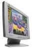
This
product
uses
74HC4053
as
a
signal
switch
in
order
to
support
Composite
SYNC
and
SYNC
on
Green
Timings.
The
MPU(1C25)
in
this
product
provides
the
differentiation
function
to
the
Composite
SYNC,
allowing
for
a
simpler
SYNC
processor
circuit
design.
The
free
run
function
in
this
product
allows
the
user
to
determine
if
the
input
signal
is
out
of
the
specified
range.
When
separated
SYNC
is
detected
through
the
V
-in
and
H
-in,
MPU
will
set
both
the
H
-select
and
V
-select
to
low
level.
If
the
composite
SYNC
is
detected,
the
H
-select
is
low
level
and
V
-
select
will
be
high
level.
If
the
SOG
is
detected,
both
H
-select
and
V
-select
are
in
high
level.
V-com
is
the
vertical
SYNC
separated
from
the
Composite
SYNC
through
MPU.
If
the
input
signal
is
out
of
the
specified
range,
the
free
run
mode
will
be
activated.
The
free
run
SYNC
comes
from
the
pin
39
and
40
of
ICO2.
In
this
state,
the
HYNC-cut
signal
is
low
level
and
pin
1
of
IC06
is
at
a
high
level.
If
free
run
enable
is
also
high,
then
V
-free
and
H
-free
will
activate
the
free
run
mode.
Page
14
CONFIDENTIAL-
DO
NOT
COPY