ViewSonic VE150 Service Manual - Page 24
Trouble, Shooting, Chart
 |
View all ViewSonic VE150 manuals
Add to My Manuals
Save this manual to your list of manuals |
Page 24 highlights
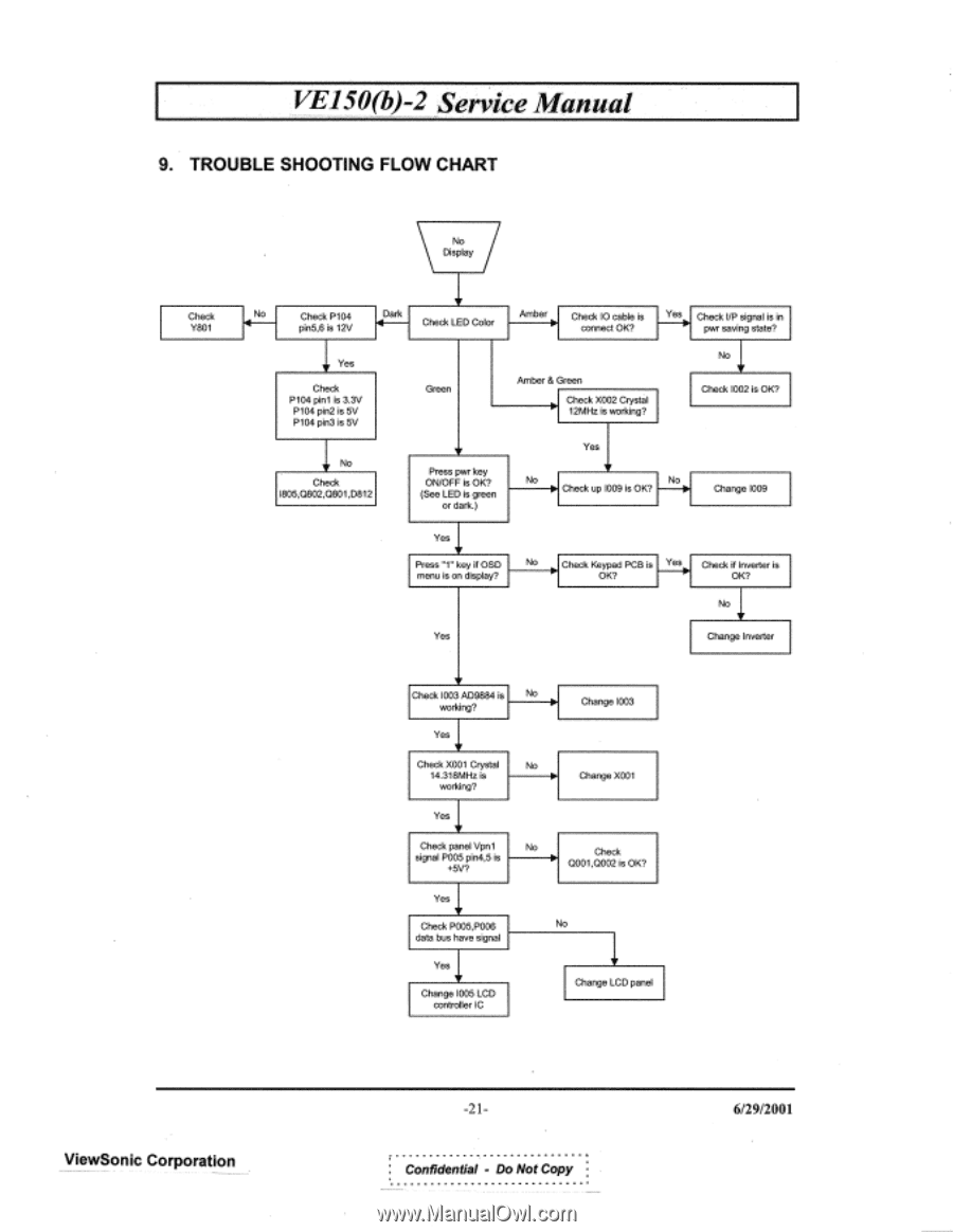
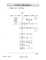
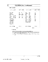
VE150(b)-2 Service Manual 9. TROUBLE SHOOTING FLOW CHART No Display Check Y801 • No Check P104 pin5,6 is 12V Dark Check LED Color Amber Check 1O cable is Y connect OK? Check VP signal is in pwr saving state? V Yes Check P104 pin/ is 3.3V P104 pin2 is 5V P104 pin3 is 5V V No Check 1805,O802,O801,D812 Green Amber & Green Check X002 Crystal 12MHz is working? No V Check 1002 is OK? V Press pwr key ON/OFF is OK? (See LED is green or dark.) Yes V No Ow Check up 1009 is OK? No Or• Change 1009 Yes 'V Press "1" key if OSD menu is on display? Yes No 10. Check Keypad OK? PCB is Yes ► Check if Inverter is OK? No V Change Inverter V Check 1003 AD9884 is No working? Yes V Check X001 Crystal No 14.318MHz is working? Change 1003 Change X001 Yes Check panel Vpn1 No signal P005 pin4,5 is +5V? Check O001,O002 is OK? Yes V Check P005,P006 data bus have signal Yes • Change 1005 LCD controller IC No • Change LCD panel ViewSonic Corporation -21Confidential - Do Not Copy 6/29/2001
-
 1
1 -
2
-
3
-
4
-
5
-
6
-
7
-
8
-
9
-
10
-
11
-
12
-
13
-
14
-
15
-
16
-
17
-
18
-
 19
19 -
 20
20 -
 21
21 -
 22
22 -
 23
23 -
 24
24 -
 25
25 -
 26
26 -
 27
27 -
 28
28 -
 29
29 -
30
-
31
-
32
-
33
 |
 |