Viking 30inch 500 VGBQ Installation Instructions - Page 11
Gas and Electrical Connection
 |
View all Viking 30inch 500 VGBQ manuals
Add to My Manuals
Save this manual to your list of manuals |
Page 11 highlights
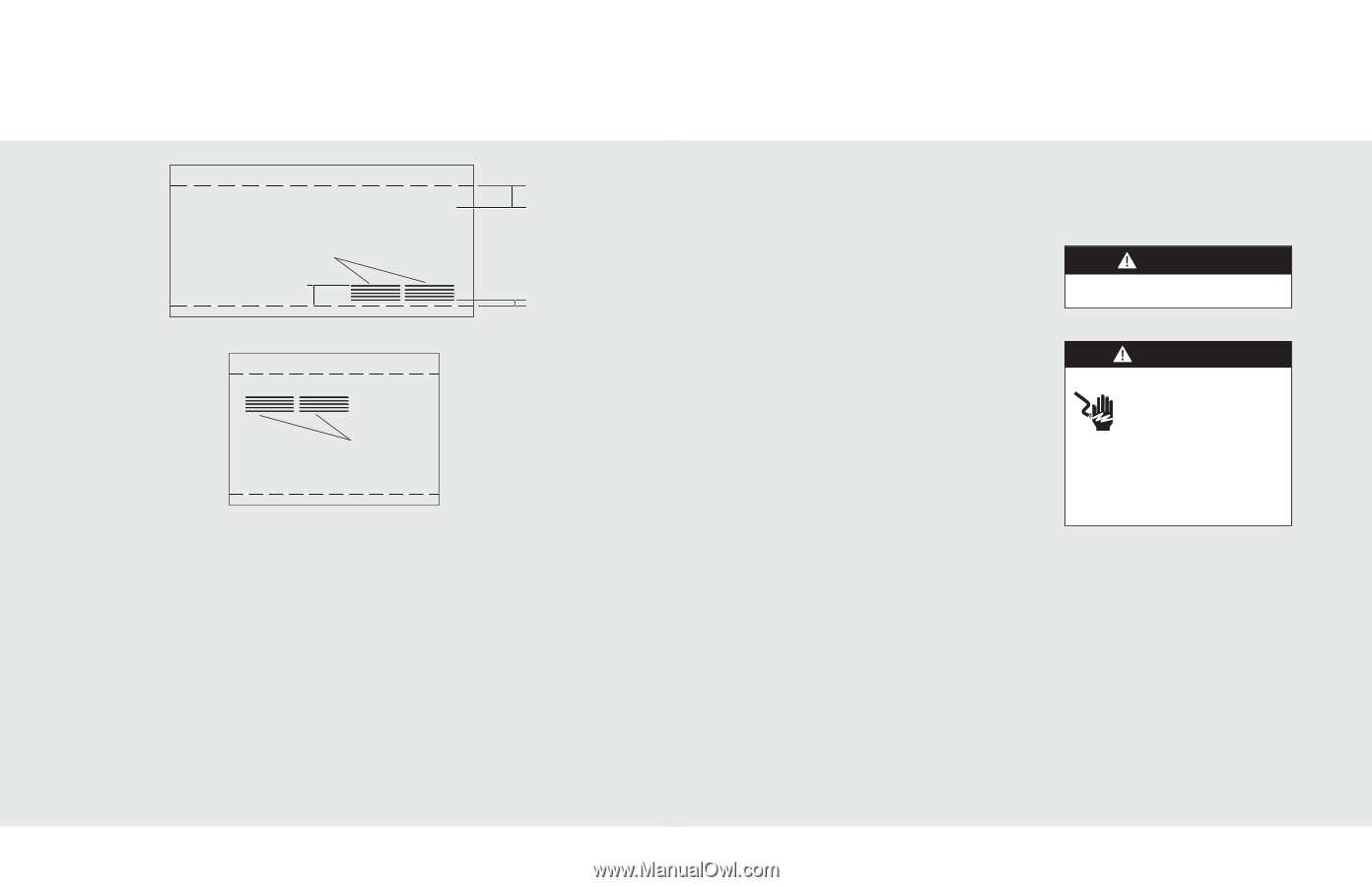
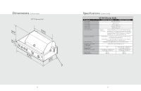
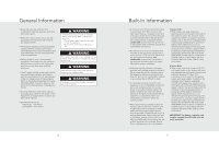
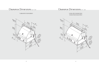
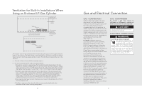
Ventilation for Built-In Installations When Using an Enclosed LP-Gas Cylinder Not more than 5.00 inches from inside bottom of countertop. 5.00 inch maximum Vents 5.00 inch maximum All vents no more than 5.00 inches above the floor of the installation. 1.00 inch maximum Bottom Vent not more than 1.00 inch from inside floor of installation. Vents located on sidewall An enclosure for an LP-gas cylinder shall be ventilated by openings at both the upper and lower levels of the enclosure. The effectiveness of the opening(s) for purposes of ventilation shall be determined with the LP-gas supply cylinder in place. This shall be accompanied by one of the following: a. One side of the enclosure shall be completely open; or b. For an enclosure having four sides, a top and a bottom: 1. At least two ventilation openings (See Part IV, Definitions) shall be provided in the side walls of the enclosure, located within 5 in. (217 mm) of the top of the enclosure, equally sized, spaced at a minimum of 90 degrees (1.57 rad), and unobstructed. The opening(s) shall have a total free area of not less than 1 in2/lb (1.42 cm2/kg) of stored fuel capacity. 2. Ventilation opening(s) shall be provided at floor level at rear of the enclosure and shall have a total free area of not less than 1/2 in2/lb (7.1 cm2/kg) of stored fuel capacity. The bottom of the openings shall be 1 in. (25.4 mm) or less from the floor level and the upper edge no more than 5 in. (127 mm) above the floor level. The openings shall be equally sized, spaced at a minimum of 90 degrees (1.57 rad) and unobstructed. 3. Every opening shall have minimum dimensions so as to permit the entrance of a 1/8 inch (3.2 mm) diameter rod. 4. Ventilation openings in the side walls shall not communicate directly with other enclosures of the outdoor cooking gas appliance. 20 Gas and Electrical ConneDcAtNiGoEnR GAS CONNECTION Verify the type of gas supply to be used, either natural or LP, and make sure the marking on the grill rating plate agrees with that of the supply. Never connect an unregulated gas line to the appliance. An installer supplied gas shut-off valve must be installed in an easily accessible location. All installer supplied parts must conform to local codes, or in the absence of local codes, with the National Electrical Code, ANSI/NFPA 70 and the National Fuel Code, ANSI Z223.1/NFPA 54. In Canada: Installation must be in accordance with the current CSA-B149.1, Natural Gas Installation Code or CSAB149.2, Propane Installation Code and/or local codes. All pipe sealants must be an approved type and resistant to the actions of LP gas. Never use pipe sealant on flare fittings. All gas connections should be made by a competent technician and in accordance with local codes and or ordinances. In the absence of codes, the installation must comply with the National Fuel Gas Code ANSI Z223.1/NFPA 54. The gas grill and its individual shut-off valve must be disconnected from the gas supply piping system during any pressure testing of that system at test pressures in excess of 1/2 PSIG (3.5 kPa). The gas grill must be isolated from the gas supply piping system by closing its individual manual shut-off valve during any pressure testing of that system at test pressures equal to or less than 1/2 psi (3.5 kPa). Built-in installations must be plumbed using a fixed/hard line if the unit is going to be operated at a distance exceeding 3 feet (0.91 meters) from the fuel supply per ANSI Z21.24 CSA. GAS CONVERSION To convert a grill from natural to LP/Propane or LP/Propane to natural, you MUST use conversion kit sold seperately. CAUTION Conversions should only be performed by an authorized service technician. ELECTRICAL CONNECTION WARNING ELECTRICAL SHOCK HAZARD This appliance is equipped with a 3' (91.4 cm) 3-prong power cord with a grounding plug for your protection FOR YOUR SAFETY against shock hazard and should be plugged directly into a properly grounded receptacle. Do not cut or remove the grounding prong from this plug. This unit is not fused and installer must install a GFI. Unit must be grounded in accordance with local codes or with the National Electrical Code ANSI/NFPA 70, or the Canadian Electrical Code, CSA C22.1. 21
-
 1
1 -
2
-
3
-
4
-
5
-
 6
6 -
 7
7 -
 8
8 -
 9
9 -
 10
10 -
 11
11 -
 12
12 -
 13
13 -
 14
14 -
 15
15 -
 16
16 -
17
-
18
 |
 |