Viking VDB450SS Installation Instructions - Page 10
Installation Procedure cont'd.
 |
View all Viking VDB450SS manuals
Add to My Manuals
Save this manual to your list of manuals |
Page 10 highlights
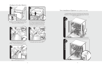
Installation Procedure (cont'd.) 5b Front Panel Attached Front Panel Removed Remove front panel to access the front leveling legs. 5c 6 Leveling legs will be raised during shipping. Adjust To check level, front to back, pull the top rack half-way front leveling legs down by using a 1/4 drive ratchet. out of unit. The rack should remain stationary and not 6a When the adjustment nut is visibleF, croomnpt lPetaentehel Attachedmove in or out. After unit is level, replace front panel lowering of the legs from the top. When the legs are and ensure overflow channel is in place. down, tighten the locking nut on the top of the leg. To level center rear leg, see Step 5a. Front Panel Removed 18 Installation Procedure (cont'd.) 7 7b Attach screws through trim pieces into cabinets. (select models). 8 Minimum 20" (50.8 cm) from floor Install High Loop Clip, which is provided, a minimum of 20" (50.8 cm) from the floor. 10A Attach screws through bracket into cabinets (select models). 9 1.0" (2.5 cm) Cut here for 5/8" (1.6 cm) Cut here for 3/4" (1.9 cm) Identify discharge connection size; cut line to correct size and connect. Clamp if necessary. 10B (Discharge with food waste disposer) 19 (Standard discharge)
-
 1
1 -
2
-
3
-
4
-
 5
5 -
 6
6 -
 7
7 -
 8
8 -
 9
9 -
 10
10 -
 11
11 -
 12
12
 |
 |
